Robotic Barrier Construction through Weaved, Inflatable Tubes
Robotic Barrier Construction through Weaved, Inflatable Tubes
In this paper, we investigate the use of extruded tubes weaved around existing environmental features to quickly assemble light-duty barriers, e.g. against wind or snow. By extruded tubes, we are referring to the recent advancement in ‘vine-robots’ where everted, flexible polymer tubes can be inflated several meters out from their deployment mechanism.
In this article, we present a mechanism and related path planning algorithm to construct light-duty barriers out of extruded, inflated tubes weaved around existing environmental features. Our extruded tubes are based on everted vine-robots and in this context, we present a new method to steer their growth. We characterize the mechanism in terms of accuracy resilience, and, towards their use as barriers, the ability of the tubes to withstand distributed loads. We further explore an algorithm which, given a feature map and the size and direction of the external load, can determine where and how to extrude the barrier. Finally, we showcase the potential of this method in an autonomously extruded two-layer wall weaved around three pipes. While preliminary, our work indicates that this method has the potential for barrier construction in cluttered environments, e.g. shelters against wind or snow. Future work may show how to achieve tighter weaves, how to leverage weave friction for improved strength, how to assess barrier performance for feedback control, and how to operate the extrusion mechanism off of a mobile robot.
Publication:
Robotic Barrier Construction through Weaved, Inflatable Tubes
Heather Jin Hee Kim*, Haron Abdel-Raziq*, Xinyu Liu, Alexandra Young Siskovic, Shreyas Patil, Kirstin H. Petersen, and Hsin-Liu Cindy Kao. (*These authors contributed equally to this work.)
International Conference on Intelligent Robots and Systems (IROS 2023).
PDF
Project Credits: The Hybrid Body Lab, Cornell University in collaboration with the Collective and Embodied Intelligence Lab, Cornell University
Research Team: Heather Jin Hee Kim*, Haron Abdel-Raziq*, Xinyu Liu, Alexandra Young Siskovic, Shreyas Patil, Prof. Kirstin H. Petersen (CEI Lab Director), and Prof. Hsin-Liu Cindy Kao (HBL Lab Director). (*These authors contributed equally to this work.)
This work was funded by a Packard Fellowship for Science and Engineering and NSF grants CNS-2042411 and IIS-2047249.
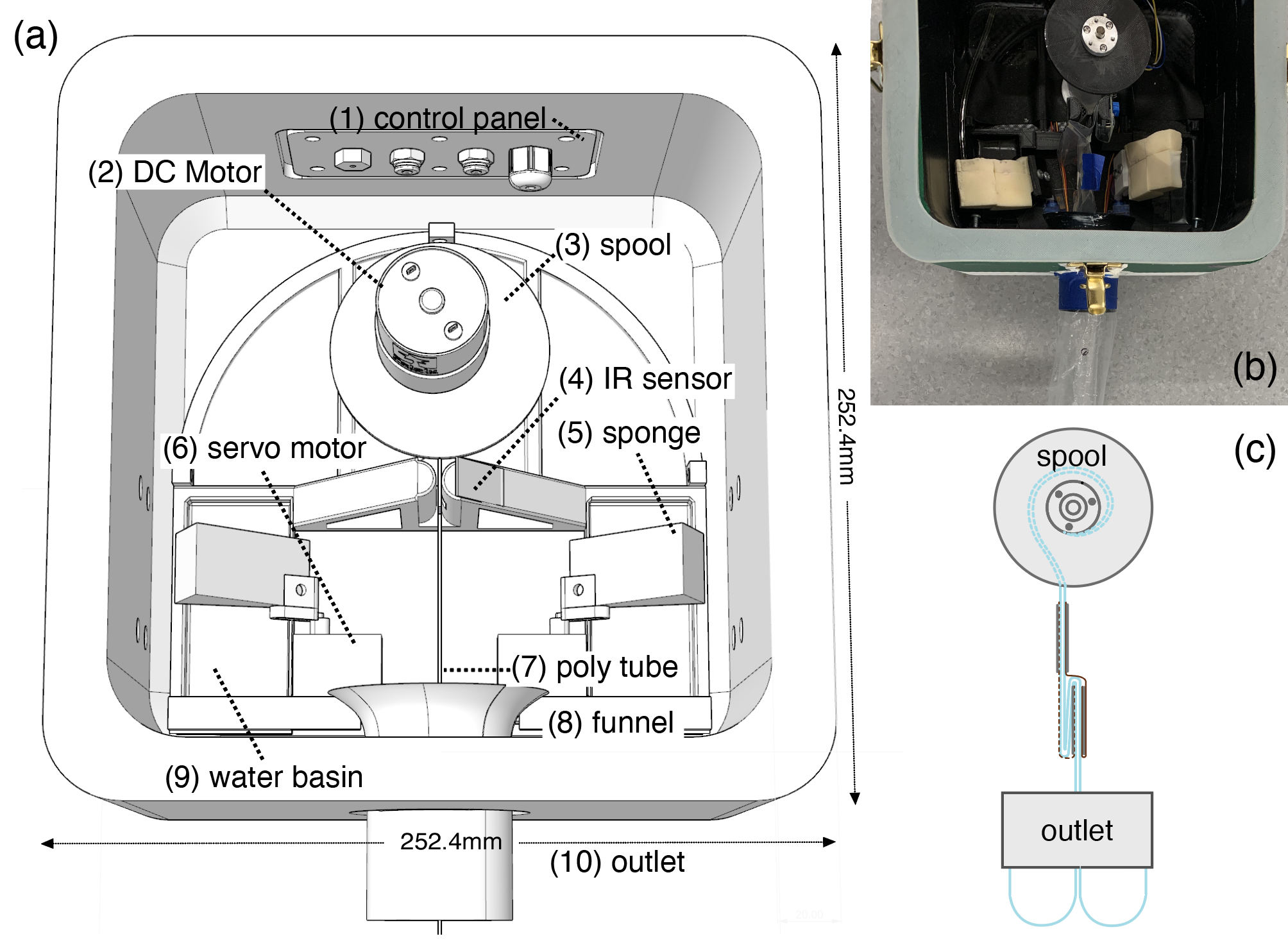
An exploded view of the extrusion mechanism used in this work is shown in (a). Manufactured chassis and components are photographed in (b). A simplified schematic of the reeled tube and fold is shown in (c).
We manufactured the (rigid) chassis using PLA filament on a low-end 3D printer (Lulzbot TAZ 6 with a 0.8mm nozzle). The chassis was composed of a simple cube box with a lid, of side length ∼250mm and 20mm thick walls to withstand high internal pressure. We took several measures to secure an airtight seal: 1) we configured the printer to add 10 perimeter layers and heat treated the surface of the printed parts to avoid gaps between extruded layers; 2) we applied caulk around all screw holes to keep the positive pressure contained to the internal chamber; and 3) we secured the lid using four draw latches and a 5mm thick rim of Ecoflex 00-30 polymer. Inside the chassis we mounted a geared DC motor (Polulu item number 4744), and attached its output shaft to a 3D printed spool using a 2-sided coupler and a non-flanged ball bearing from Servocity (1600 Series). The tube extruded out through a 50mm hole with a 3D printed funnel to avoid snagging.
We mounted all control circuitry on the outside of the chassis. This circuitry included an Arduino Uno and a one-directional motor driver composed of an Nchannel MOSFET and some resistors. Finally, we inflated the robot mechanism using a Campbell Hausfeld FP209402 compressor.

(a) Example fold. (b) Simplified fold model. (c) Measured and modeled correlation between fold length Lfold and angle θ. Measured data indicates mean and standard deviation over 5 successful trials.
The fold length determines how far the tube will bend when it is pressurized and one side is released. Each data point in the graph shows the mean and standard deviation of 5 successful releases.

Steering mechanism based on an active extension of the tube. (a-b) The tube is pre-folded at regular intervals using either method (a) or (b). Folds are held in place by a thread on each side of the tube. (c) Example of a real fold. (d) Concept animation. If one side of the fold is released, the tube will bend in the direction of the remaining thread, when pressurized and extruded.
To weave the tube back and forth between existing environmental features, we must be able to steer the direction of extrusion in 2D. More specifically, given the need for a barrier, we assume that each inflated tube will consist predominantly of long straight segments, interspersed by a brief series of discrete bends large enough to direct the extrusion in the opposite direction around the following feature. We also assume that the barrier material is expendable, i.e. that there is no need to retract and/or reconfigure the tube once in place

a) Snapshots from the demonstration of two weaved, inflated barrier walls. b) Pillar R3 was moved to examine mechanism resilience to map errors.
To demonstrate the overall system concept, we placed the extrusion/steering mechanism in front of three pipes. The position of the pipes informed which folds to release, and we executed this sequence on two opposing, layered weaves (Fig. 6(a)). Note that the second tube extruded slower than the first, because the compressor had exhausted much of its air supply. Furthermore, in the demonstration, we extruded tubes from either end of the structure, but these might as well have been extruded from the same side.

Example shelter wall composed of inflated tubes interleaved between existing environmental features.