Featured
Shieldex 235/36 dtex 4 ply +B Conductive Thread
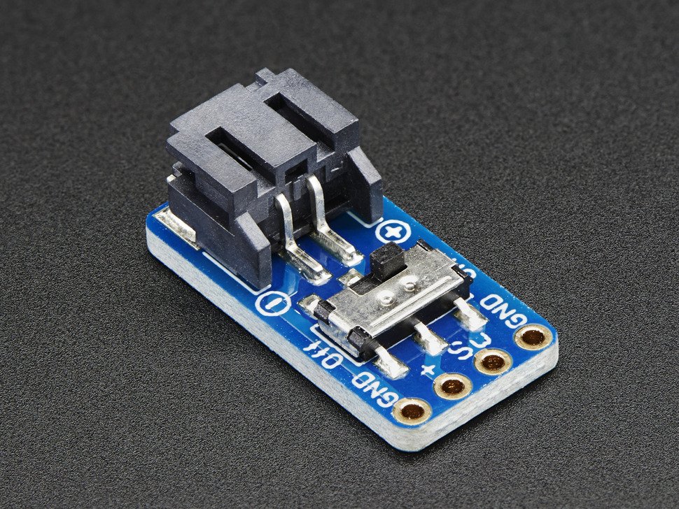
SkinLink Toolkit: MCU module, 2 NeoPixel RGB LED modules, connector modules
3D printed comb enclosure
3D printed anchor
Clear nail polish
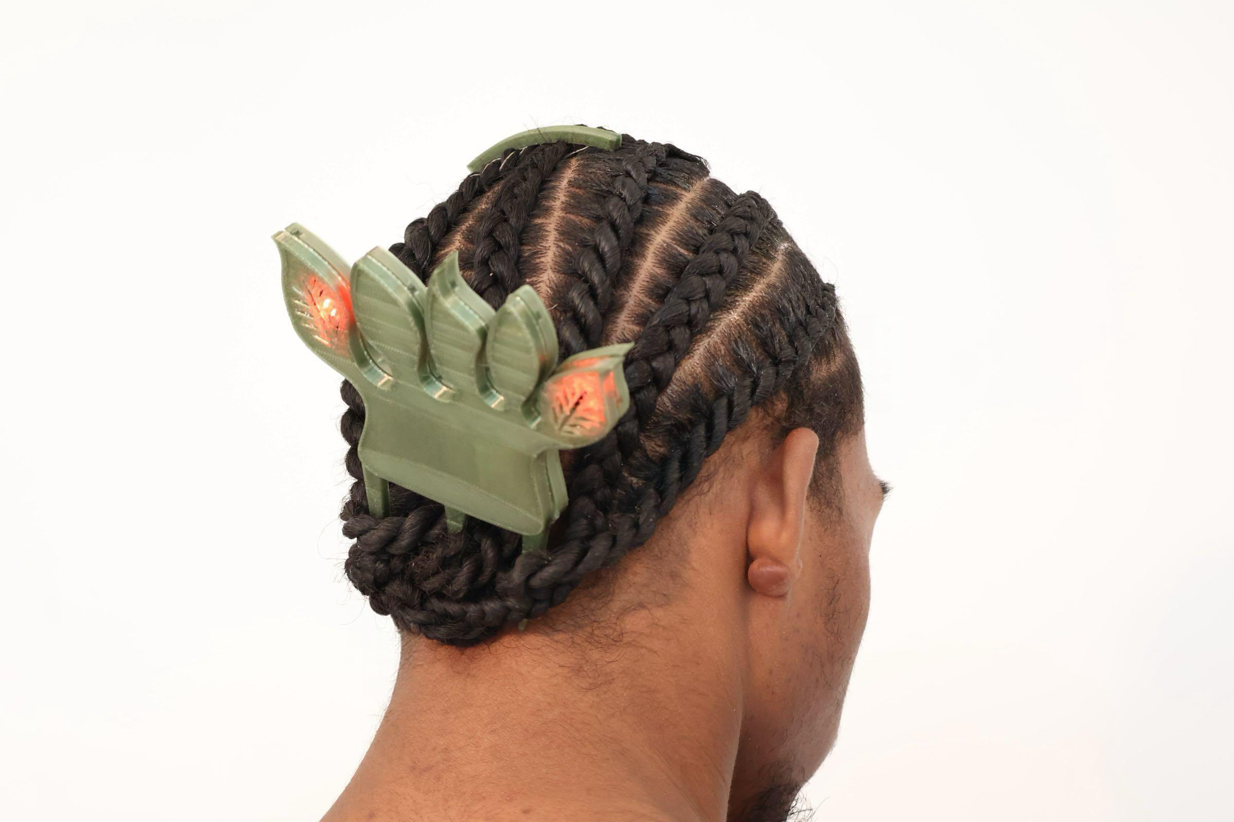
Add six strands of conductive threads to the anchor, coat the top 3cm of conductive thread with clear nail polish to insulate them.
Use the anchor to separate the conductive threads, seprate the hair into three strands and put one conductive thread into each of the strands
Braid two dutch braids, ensure the conductive threads are not shorting during the braiding process by using a multimeter to test continuity.
Solder 1MOhm resistor to the SkinLink connector modules based on the circuit diagram from https://www.mdpi.com/1424-8220/18/11/3775
Assemble SkinLink modules as shown in the image below
Connecting each end of the conductive thread to the SkinLink hardware through crimps.
Insert the comb to the bottom of the braids.
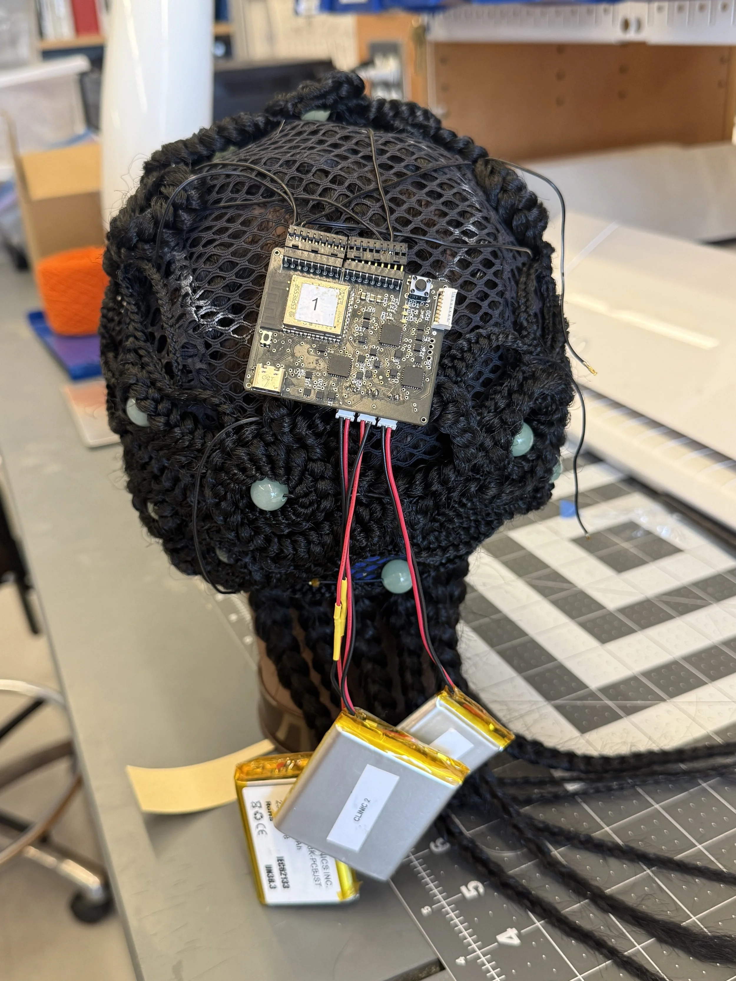
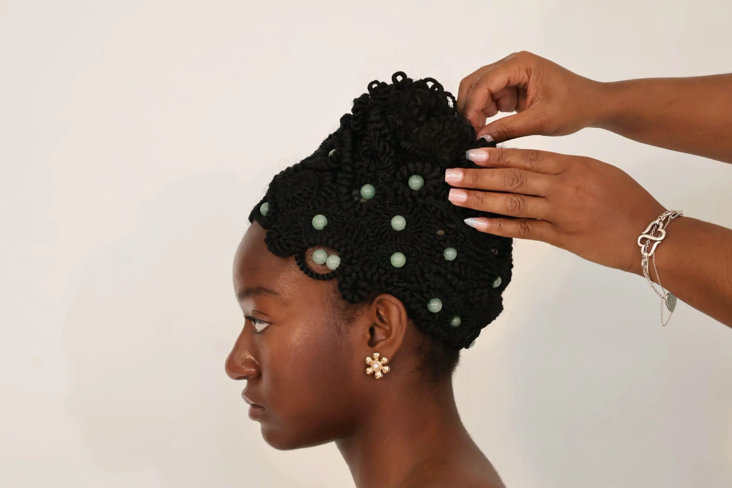
Premade Crochet Braids (16in or longer)
Large Mesh Elastic Crochet Cap
12mm Round Beads (around 30)
6 Pieces of Shape Memory Spring, 8 cm long, 0.5cm(5mm) coil diameter , 0.15 wire diameter, Pitch: wire size x2, transition temp 45C
Sillicon covered stranded wires
Use crimp connectors to connect each end of the SMA coils for easy soldering.
Insert SMA coil into a shrink tube for easy threading.
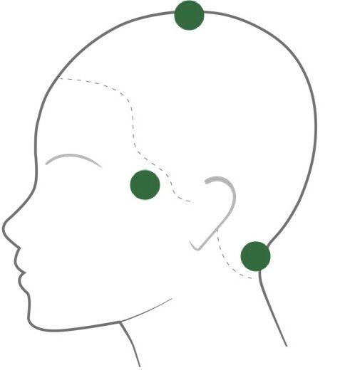
Thread the tube through the braid and beads in targeted areas: temple, top of head, and nape as shown in the diagram below.
Solder the SMA coil to wires, and connect the wires to the hardware from EdemaFlex (Link)
Drape the braids onto the mesh cap using pins, leave large area in the top of the head for hardware, and sew the braids after completing draping.
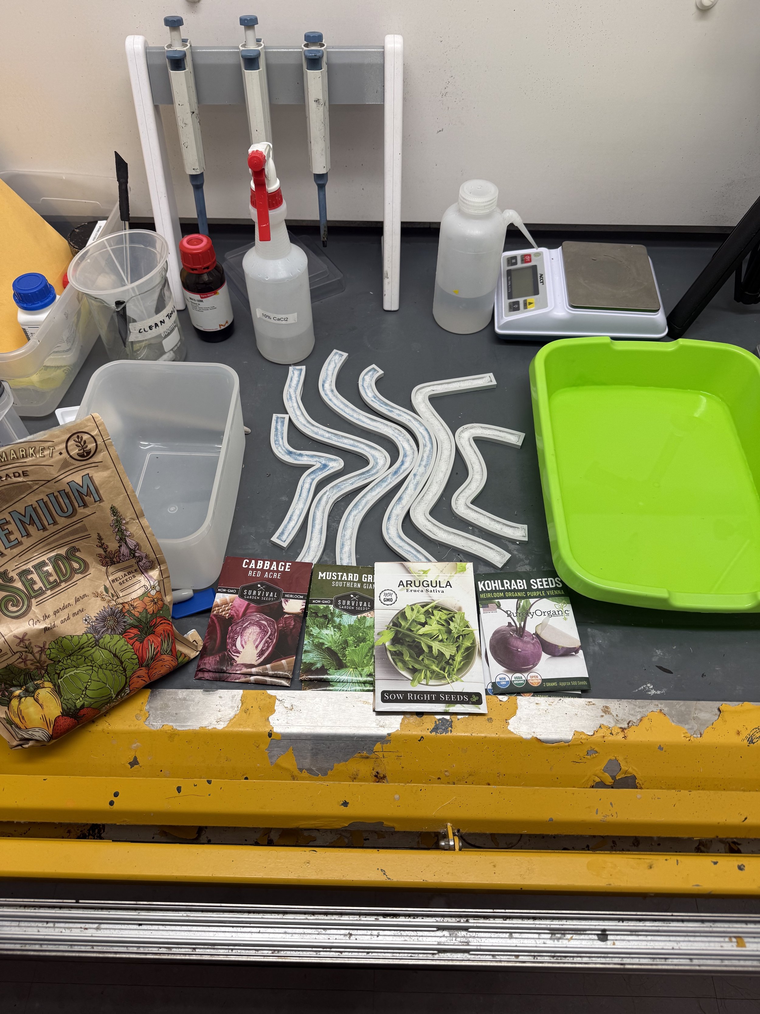
150 ml glass beaker
Syringe
4.5 g of sodium alginate
7.5 ml of glycerine
150 ml of water
3.75 ml of sunflower oil
600 ml of 10% calcium chloride solution
micro-green seeds (chia, arugula, purple cabbage, mustard, kohlrabi)
full lace human hair wig
cheese cloth
3D printed molds
food processor
vacuum sealer
a large liquid container for coagulation solution
Large plastic shower cap
Skin Safe Silicone Based Adhesive
Download the 3D models and print them with PLA filaments.
Add the glycerine, water, and oil to the food processor.
Add in alginate, mix until all lumps are removed.
Put mixture in the beaker.
Heat the mixture in a 60 degrees Celsius lab oven for 20 minutes.
Place the mixture in a vacuum sealer for 30 minutes.
Cut the cheese cloth to fit in the bottom of each mold.
Add the mixture to the syringe, and fill each mold with the mixture.
Sprinkle seeds on top of mixture, one type of seed for each mold, two molds for chia seeds
Spray each mold with a generous amount of 10% CaCl, and place the lids on them.
Put 500ml CaCl in a large container, dip each mold with the lid attached inside the solution.
Place the biofilm in a dark and humid container for 3 days.
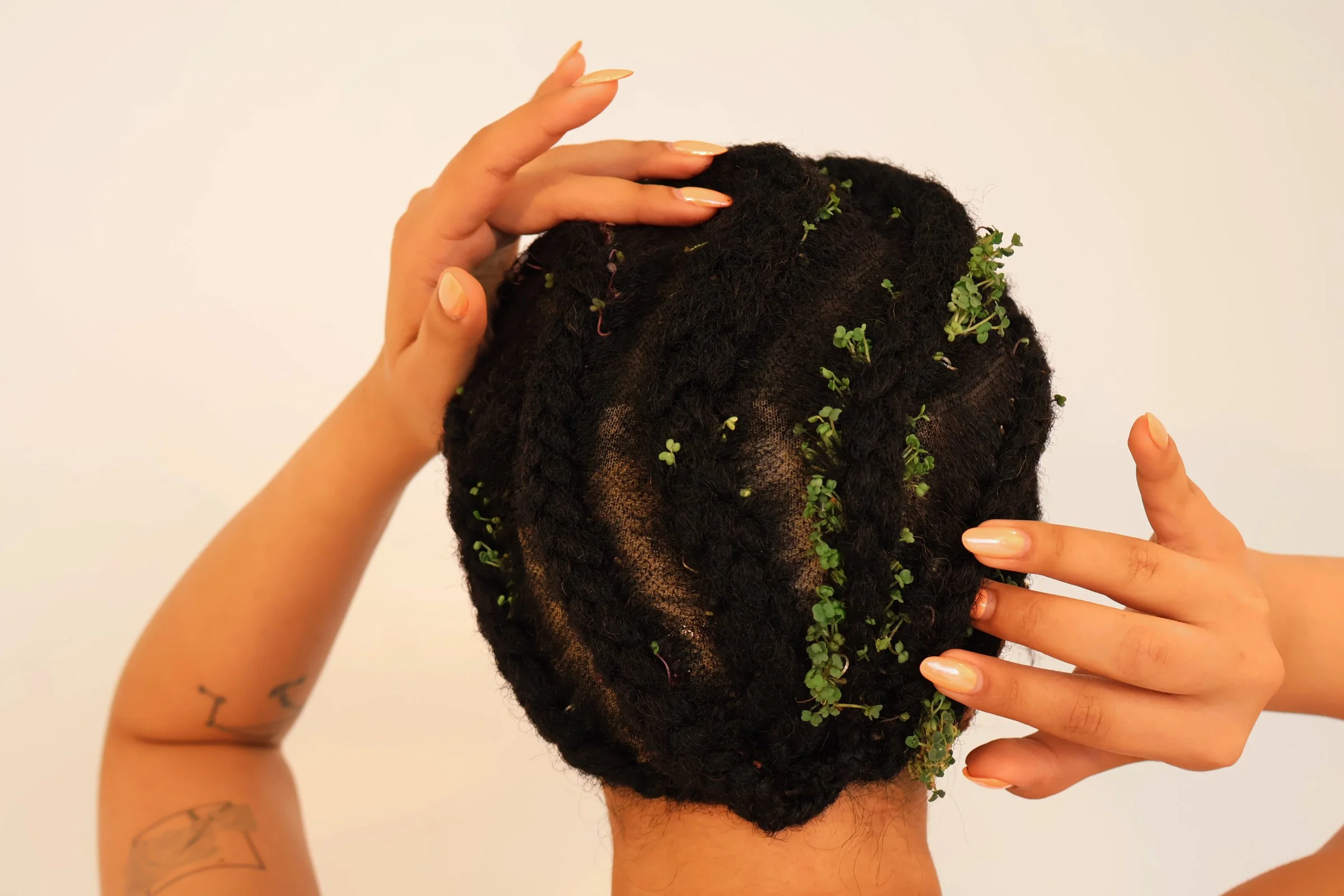
Wash, shampoo, and blow dry the wig.
Part the hair in 6 sections based on the 6 biofilm shapes.
For each braid, part each section in half, place biofilm in the center, then begin corn rows braiding.
After all braids are completed, spray the hair generously with water.
Cover wig in shower cap and placed in sunlight for 7 days.
Braid models hair into 2 french braids and wrap around the head
Wrap hair with plastic wrap
Place wig cap matching the model’s skin tone over plastic wrap
Cut excess lace from the wig.
Apply skin safe silicone adhesive all around the hairline and allow to become tacky. (Blowdryer helps)
Apply the wig and stick to adhesive one small area of the hairline at a time (hold firmly in place for 30 seconds.)
Sodium Alginate Powder
Glycerin
Sunflower Seed Oil
Distilled Water
Chia Seed
Distilled water
Calcium Chloride
Bags and bobbins for spun yarn
Fabric swatches (cotton or fleece recommended)
Embroidery needles & thread (for couching stitch)
Small loom (for weaving experiments)
Luer lock easy glide 30mL Syringe
Luer lock syringe nozzles, 12 Gauge
Rubber Spatula
Digital Scale
Food processor
Weigh boats
Vacuum sealer with container
Note: if you cannot purchase a vacuum sealer, we provide you with alternatives in the instructions.
Spray bottles
Large beakers/containers
Strainer
Mixing tools (popsicle sticks)
Before proceeding with the rest of the project, first test the quality of the seeds to make sure they do not have trouble sprouting.
Put a pinch of chia seeds in a shallow container and spray with tap water.
Place a napkin over the seeds to retain more moisture and airflow.
Spray some 5% w/v calcium chloride on top of the napkin.
Cover the container slightly.
Place the container in direct sunlight for Days 1-3.
The seeds should sprout in 3-5 days. Once they have sprouted, you may continue the tutorial.
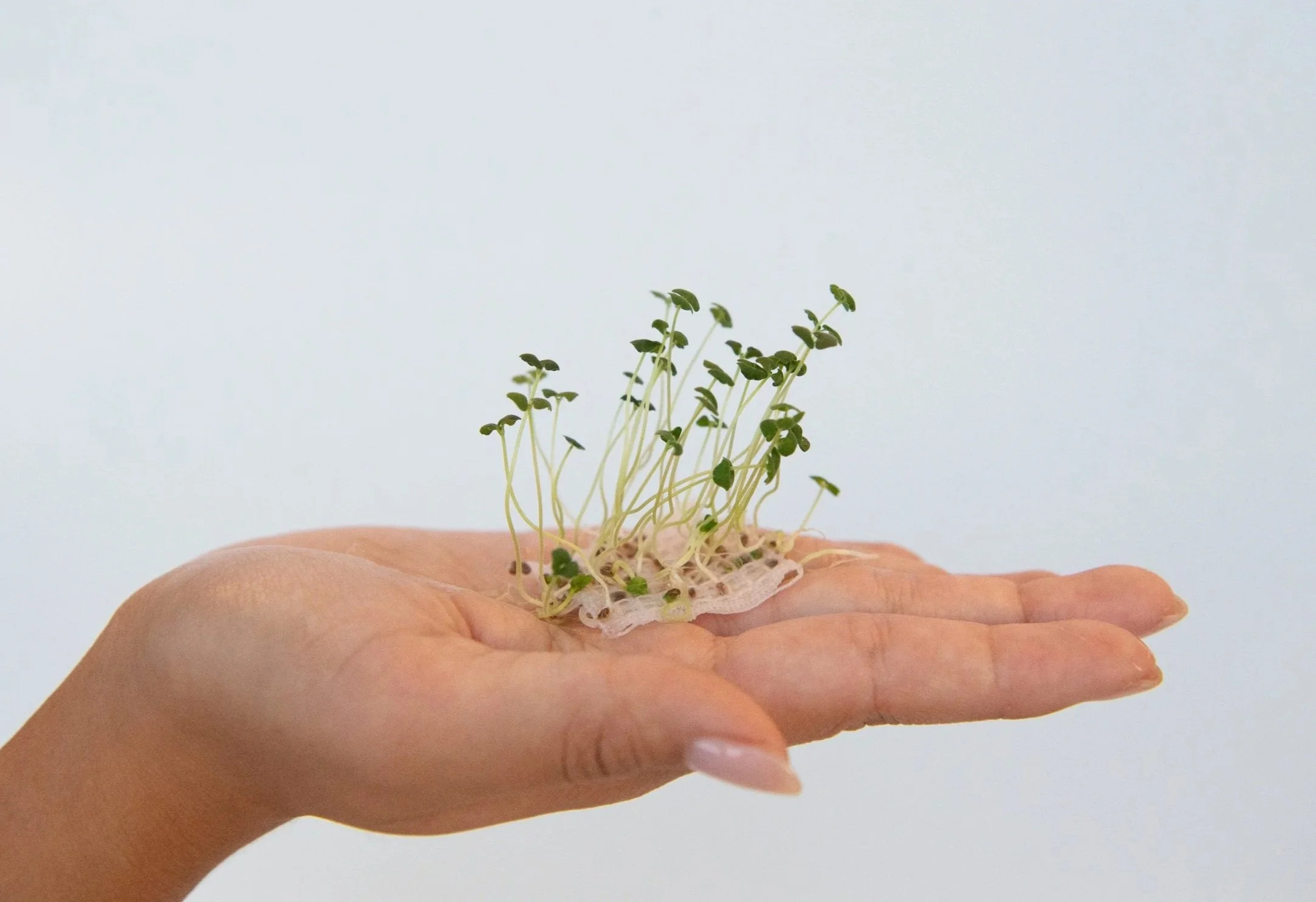
Sample of sprouted chia seeds.
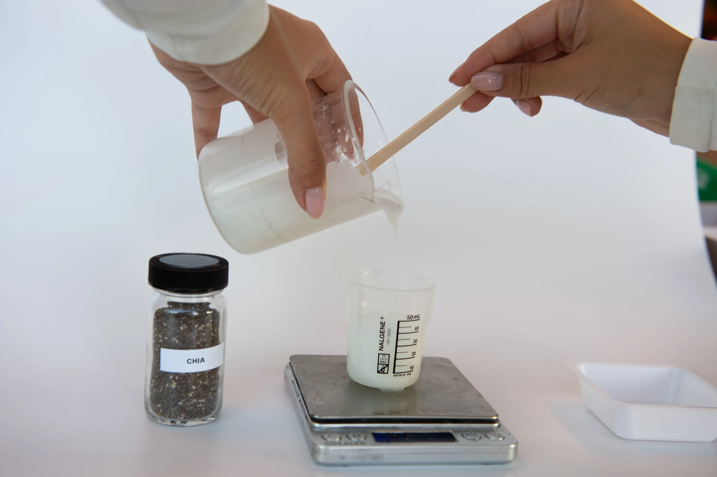
In a food processor, add 150g distilled water, 5g glycerin, and 2.5g sunflower oil
In a separate container, weigh 4g sodium alginate.
In 1-gram increments, slowly add sodium alginate into the kitchen mixer, mixing well in between each addition and scraping down the sides of the mixer.
Once all the sodium alginate has been added, ensure the mixture is smooth and homogenous in consistency. Transfer the solution to a beaker.
Optional but recommended to remove additional bacteria from solution: Sterilize the solution by placing the solution in the oven at 140F for 15 minutes to improve the success germination rate.
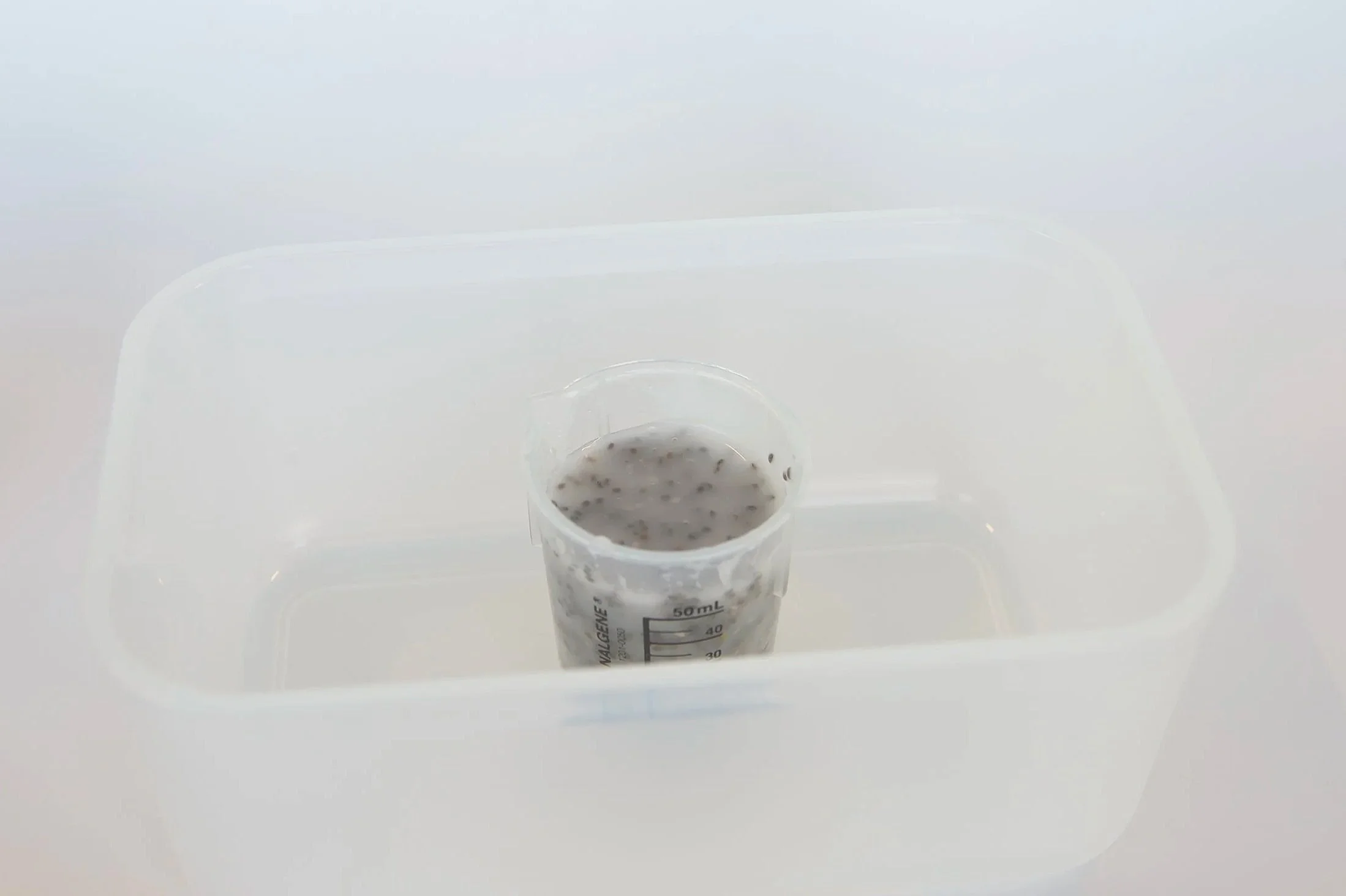
Place the solution in a vacuum chamber for ~30 minutes to remove any air bubbles to avoid breakage during spinning. Alternatively, let the solution sit in the fridge covered overnight so bubbles can rise and burst naturally. If not being used immediately, cover and refrigerate the base solution to prevent molding.
Note: The solution is now ready to use. The following steps need to be conducted 30 minutes before the wet spinning process. If not planning to wet spin immediately, stop after step 6 (to prevent chia seeds from absorbing the solution and becoming mucilaginous) and refrigerate the base solution.
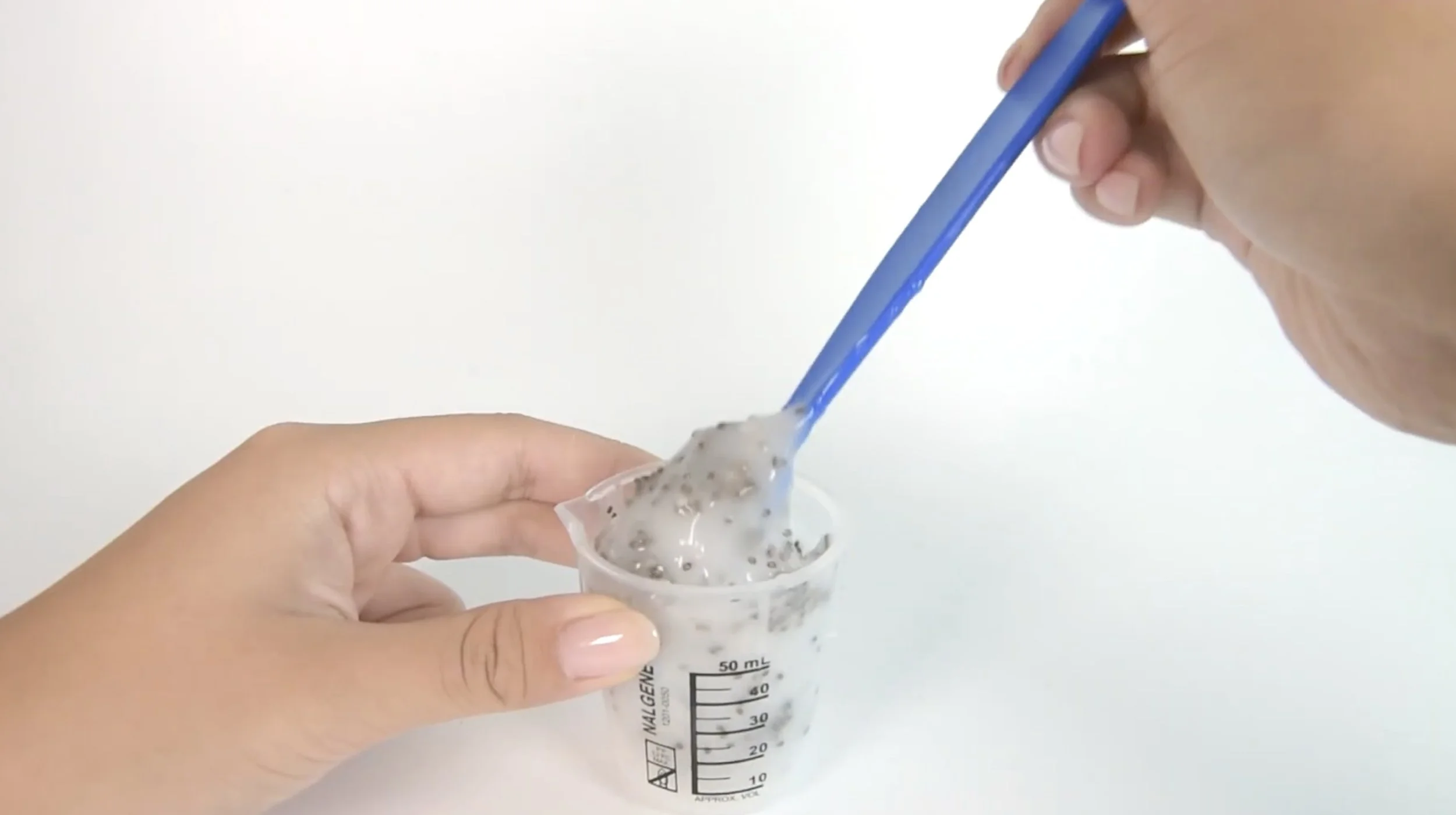
Gently and evenly mix in 16g chia seeds (or desired weight ratio).
Place the solution in a vacuum chamber for ~30 minutes to degas any air bubbles created from the previous step. Alternatively, place the container inside a heavy-duty zip bag. Seal almost fully, then suck out the air through a straw before sealing tight. This slightly reduces pressure and helps remove larger trapped bubbles.
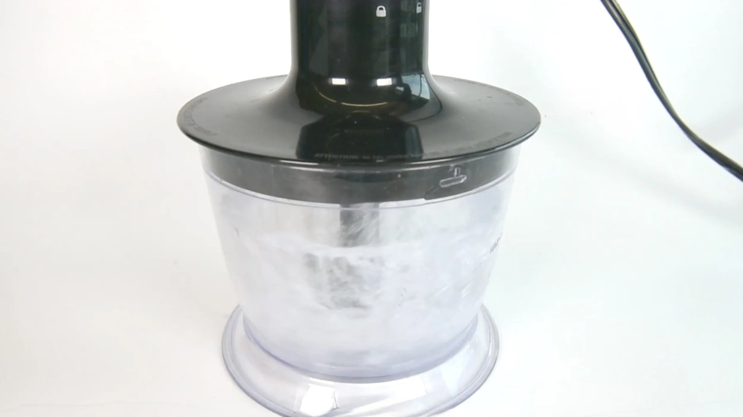
Mix base solution in food processor.
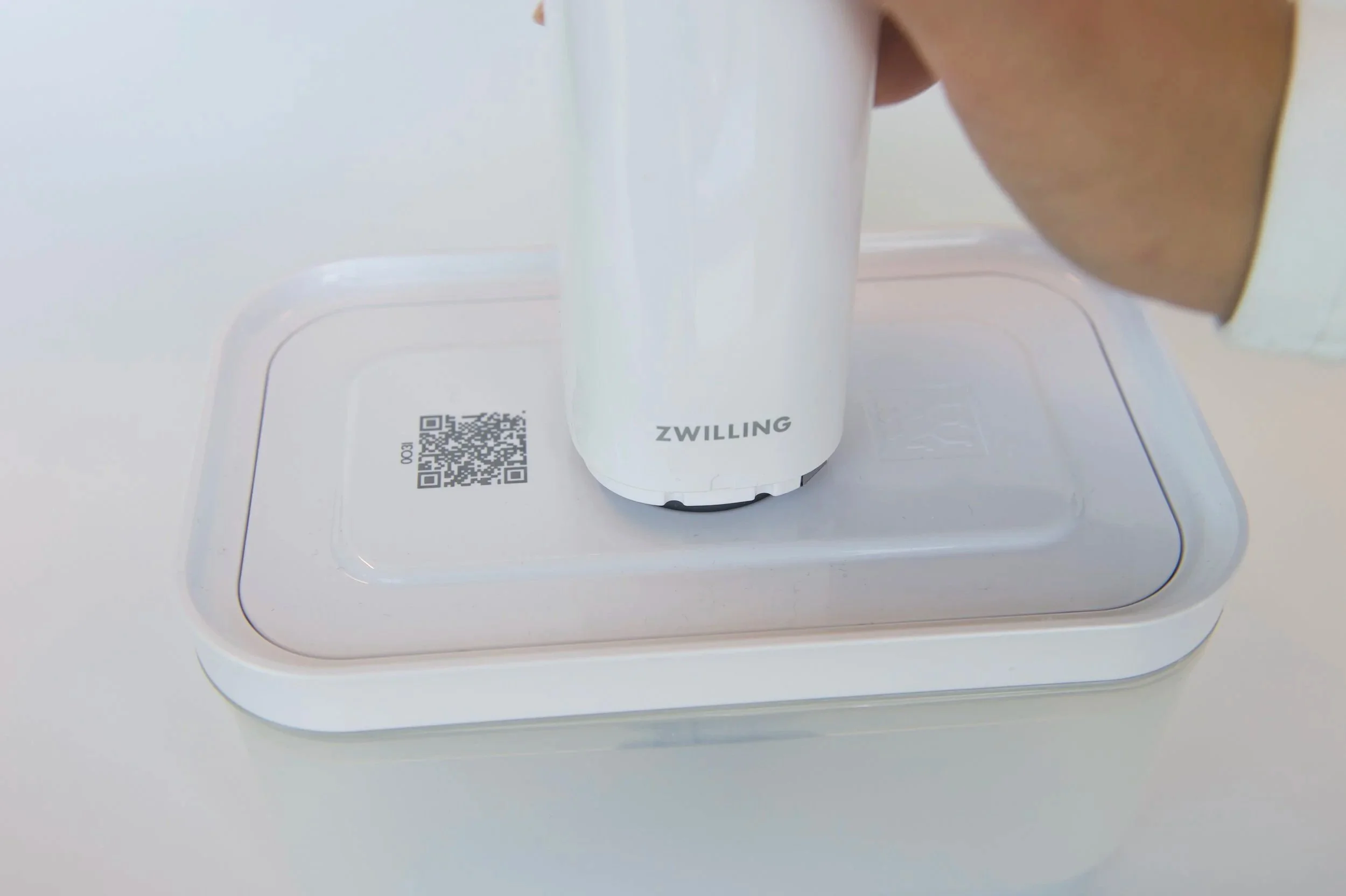
Vacuum seal solution to degas.
Prepare a 10% calcium chloride bath with distilled water for coagulation.
Weigh 10 g of CaCl₂ and add water until the total volume is 100 mL to make a 10% (w/v) solution. Stir until fully dissolved.
Transfer the chia seed solution into a syringe, then hold the syringe upright (tip facing up) to gently expel any trapped air from the tip. Attach the nozzle by twisting it clockwise until secure.
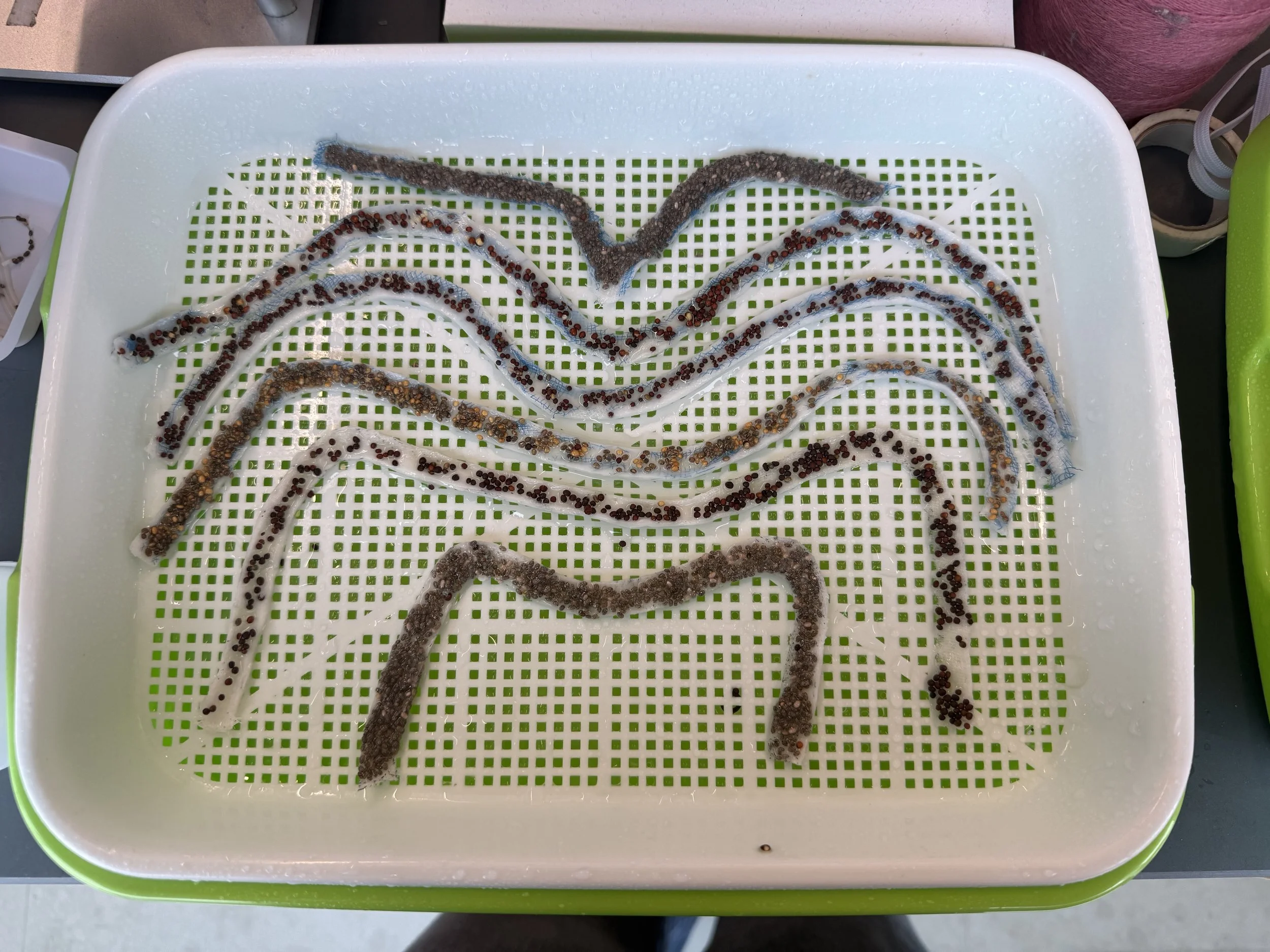
Manually extrude the solution into the stirred calcium chloride bath. Hold the syringe at a slight angle (30°) and extrude the solution in a gentle circular motion to ensure even formation in the bath.
Once extruded, wash the strands in distilled water to remove any residue from the previous bath.
Line dry the yarn overnight. The stretched length of the yarn when dried also affects the seed density.
Dried yarns can be wound on bobbins with large diameters to avoid twisted yarns for textile integration.
Prepare a 10% calcium chloride solution and pour it into a spray bottle. Spraying this solution onto surfaces and containers will help thicken any remaining residue, making it easier to clean your supplies and workspace.
Prepare a 10% calcium chloride bath with distilled water for coagulation.
Transfer the chia seed solution into a syringe and allow any air at the tip of the syringe to be expelled.
Use a desktop syringe pump to extrude the solution into the stirred calcium chloride bath. (Figure 6)
Once extruded, wash the strands in distilled water to remove any residue from the previous bath.
Line dry the yarn overnight. The stretched length of the yarn when dried also affects the seed density.
Dried yarns can be wound on bobbins with large diameters to avoid twisted yarns for textile integration.
Prepare a 10% calcium chloride solution and pour it into a spray bottle. Spraying this solution onto surfaces and containers will help thicken any remaining residue, making it easier to clean your supplies and workspace.
Video of manual extrusion.
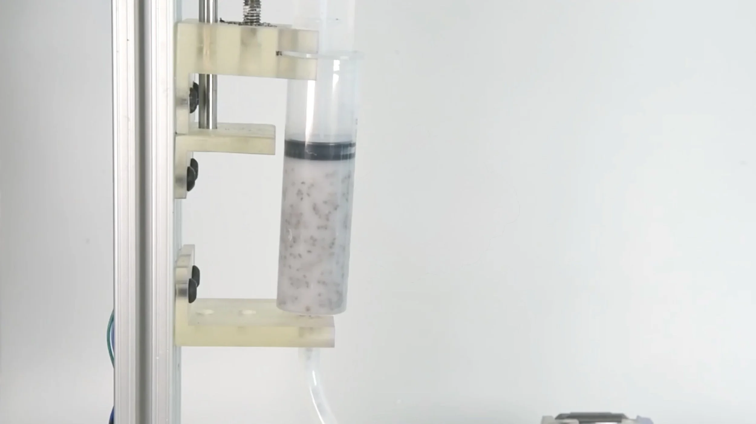
Machine extrusion.
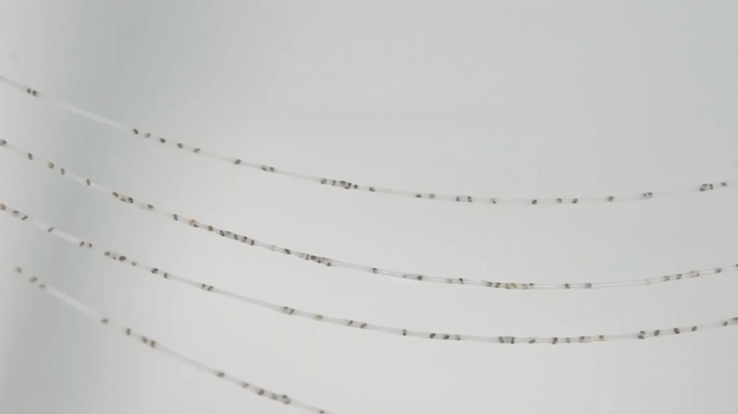
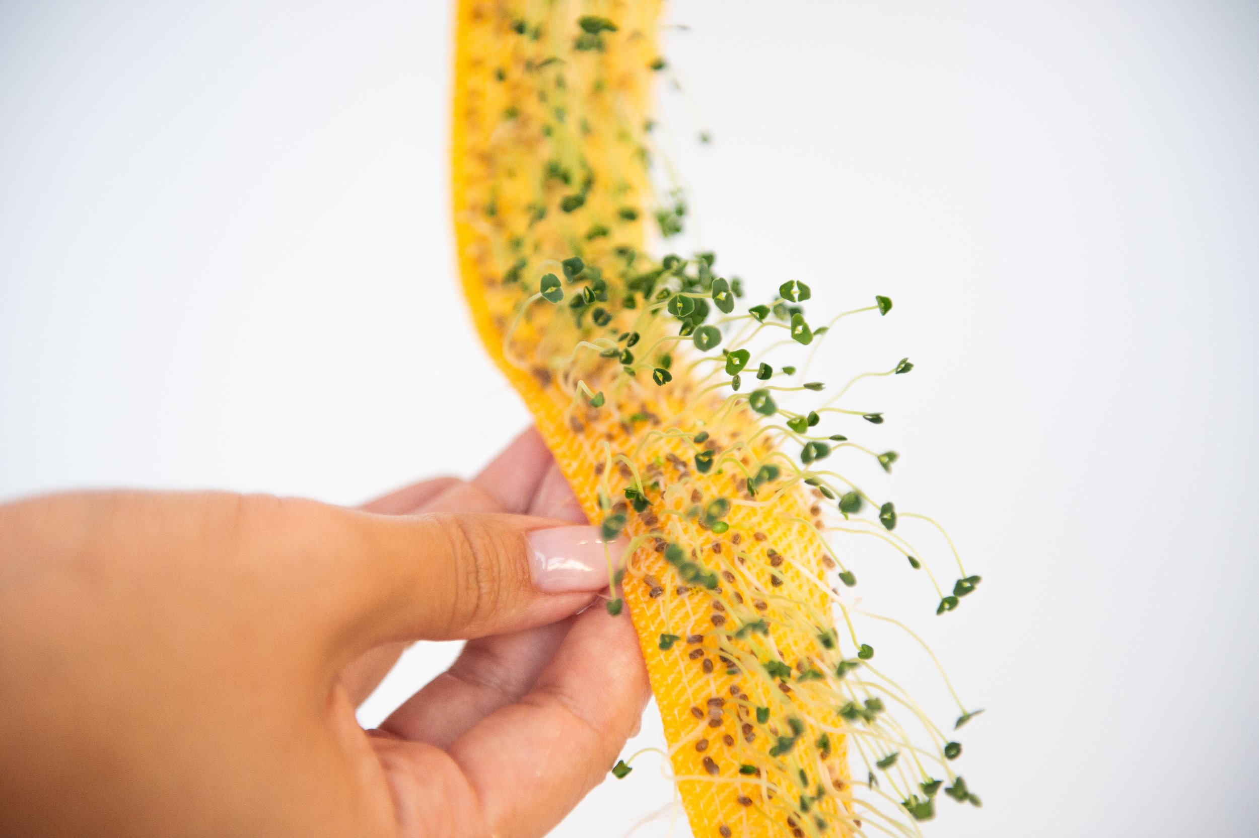
Wet-spun yarns, prior to drying.
The following textile integration steps outline different methods for embedding Seed-Integrated Hydrogel Yarns into fabric structures to balance water absorption, seed exposure, and material strength. Each approach–weaving or embroidery- offers a unique way to integrate the hydrogel yarns depending on the intended function and fabrication technique. Together, these methods illustrate how traditional textile processes can be adapted to support bio-integrated materials, merging craft-based techniques with experimental material research.
Here are our recommendations on when to use which approach for your project. Students should choose between these methods based on their fabrication tools, desired interaction with the plant growth (visible vs. embedded), and structural goals (durability vs. flexibility):
Embroidery: best if you want to attach hydrogel yarns onto an existing textile surface, allowing easy control of moisture and visibility of seed growth without disrupting the original fabric’s structure.
Weaving: integrates the hydrogel yarns directly into the weave, creating a more unified material with greater strength and stability but less flexibility.
Reference Tutorial Video: Embroidery 101: How to Embroider a Couching Stitch
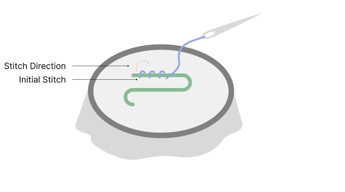
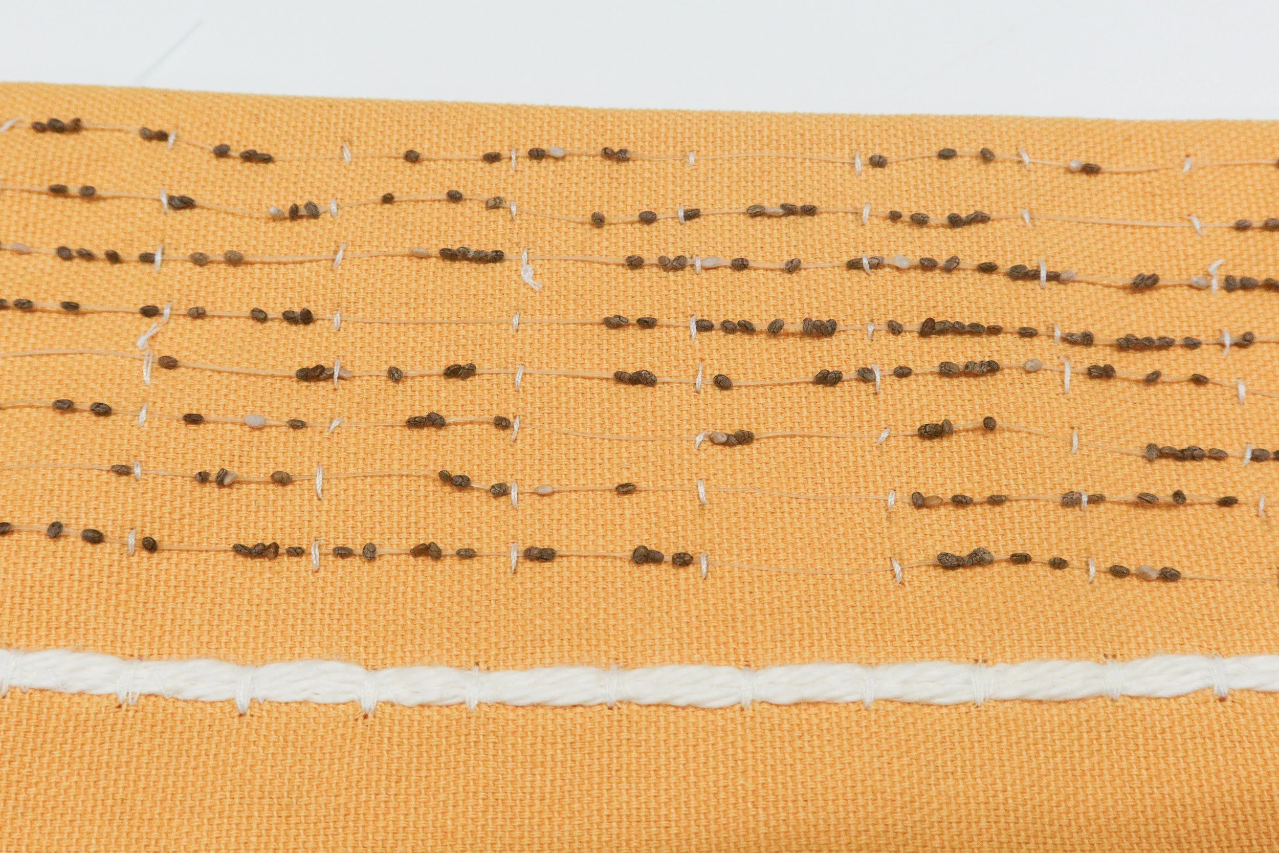
Here, we use Couching Stitch (Figure 9) as an example to provide instructions on how to use the substrate lining technique for textile integration.
Thread a needle with cotton thread.
Secure the substrate fabric tautly on an embroidery hoop
Lay the Seed-Integrated Hydrogel Yarn on top of the fabric in the desired pattern (e.g., straight line, curve, or decorative shape). It’s optional to use a pencil or chalk to mark the pattern on the fabric.
Anchor the chia fiber by bringing the needle with thread up and through the fabric from the back of the fabric.
Cross the needle over the hydrogel yarn and insert it back into the fabric, creating a small stitch over the hydrogel yarn.
Move a short distance along the fiber (~2 cm) and repeat the same stitch (steps 4 and 5)
Guide the hydrogel yarn in the desired shape or pattern you want by holding it in place while stitching.
Once the design is complete and the fiber is secured on the fabric, make the final anchoring stitch and knot the thread on the back of the fabric, trimming any excess thread.
Basic Weaving Pattern: The Seed-Integrated Hydrogel Yarns can be interlaced into a weave structure. The weave structure can be any pattern that allows for water absorption, such as plain, twill, satin, or waffle.
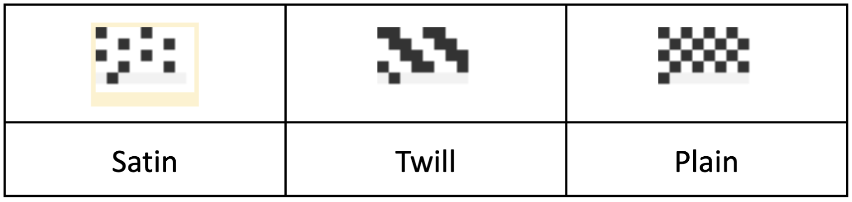
This basic weaving pattern requires the use of a hand loom which can be found here: https://helloloom.com/shop/p/hello-loom-20.
Reference Tutorial Video: https://helloloom.com/tutorials-section
Advanced Weaving Pattern:
This advanced weaving pattern requires the use of a floor loom or digital jacquard loom.
Digital Jacquard Loom Tutorial: https://www.youtube.com/watch?v=UK6IqovdKLA
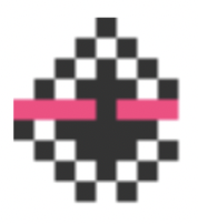
Here we use a waffle weave as an example, with a top layer tacking the Seed-Integrated Hydrogel Yarns. This pattern (A) is used in the user study and the sandal application. The magenta color represents the hydrogel yarn as weft.
To add a third layer at the bottom to integrate the tubing for watering, an additional warp-floating layer (B) could be added. The magenta color represents the hydrogel yarn as weft and the cyan color represents the tubing as weft.
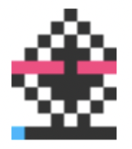
Example of hybrid layering weave.
Once you have completed the Textile Integration steps, you will need to maintain and grow the chia seeds.
Place the seed-integrated textiles in dark, shallow containers to block sunlight while ensuring airflow to prevent mold.
You can use microgreen sprouting trays or any shallow tray covered with any material that blocks light (ex: panda film, aluminum foil).
Water daily to maintain adequate moisture.
After 3-5 days, remove the material cover to expose the textiles to direct sunlight.
If the plant-integrated textiles are worn during the day, they will require more frequent watering due to increased evaporation in open environments.
This phase lasts for 5 to 14 days for chia seeds.
Optional: The plant-integrated textiles should be potted in the soil to allow the plants to continue growing into their adult stage.
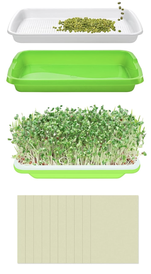
Microgreen growth container.
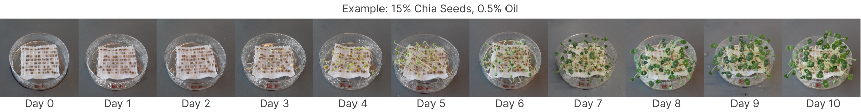
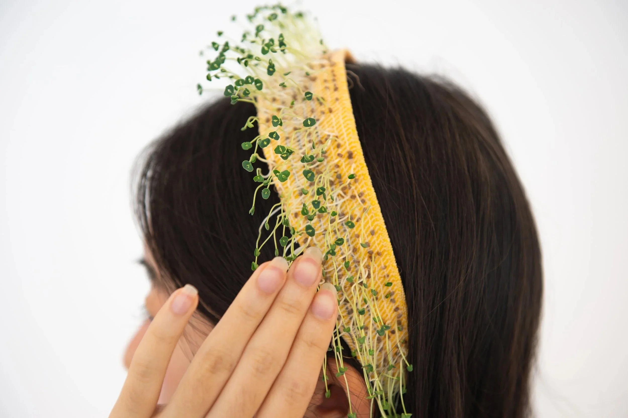
Example of 10 day growth cycle.
After making and integrating the seed-infused hydrogel yarns, the final step is to see what you can create with them! We explored this through five sample applications inspired by user feedback and rapid prototyping: touch-sensitive hairbands, self-caring hats, indoor garden throw pillows, outdoor activity sandals, and woven bags. These examples show how LivingLoom textiles can be playful, interactive, and sustainable, letting humans and plants grow together in everyday objects.
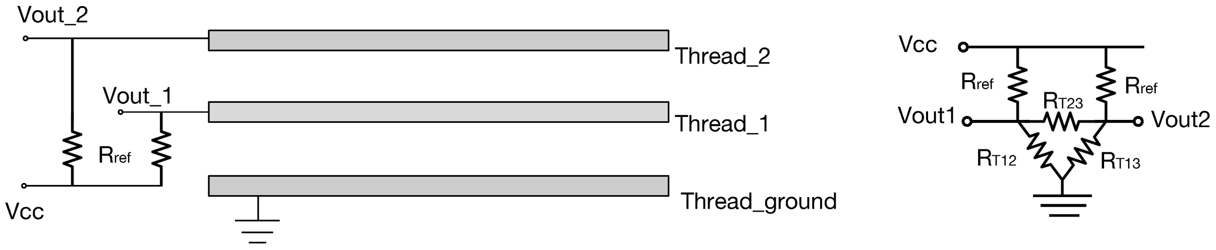
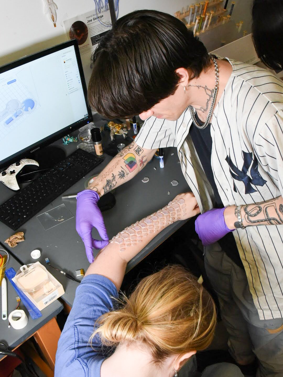
Touch-sensing hairband to “feel” the plants: The hairband is woven with seed-integrated yarns and thin conductive threads. As the chia seeds grow, the sprouts become slightly conductive, letting them act as gentle touch sensors. These sensors connect to a small microcontroller and vibration motor, so when the wearer touches the sprouts, they feel a soft vibration, making the plants feel like an extension of their own skin.
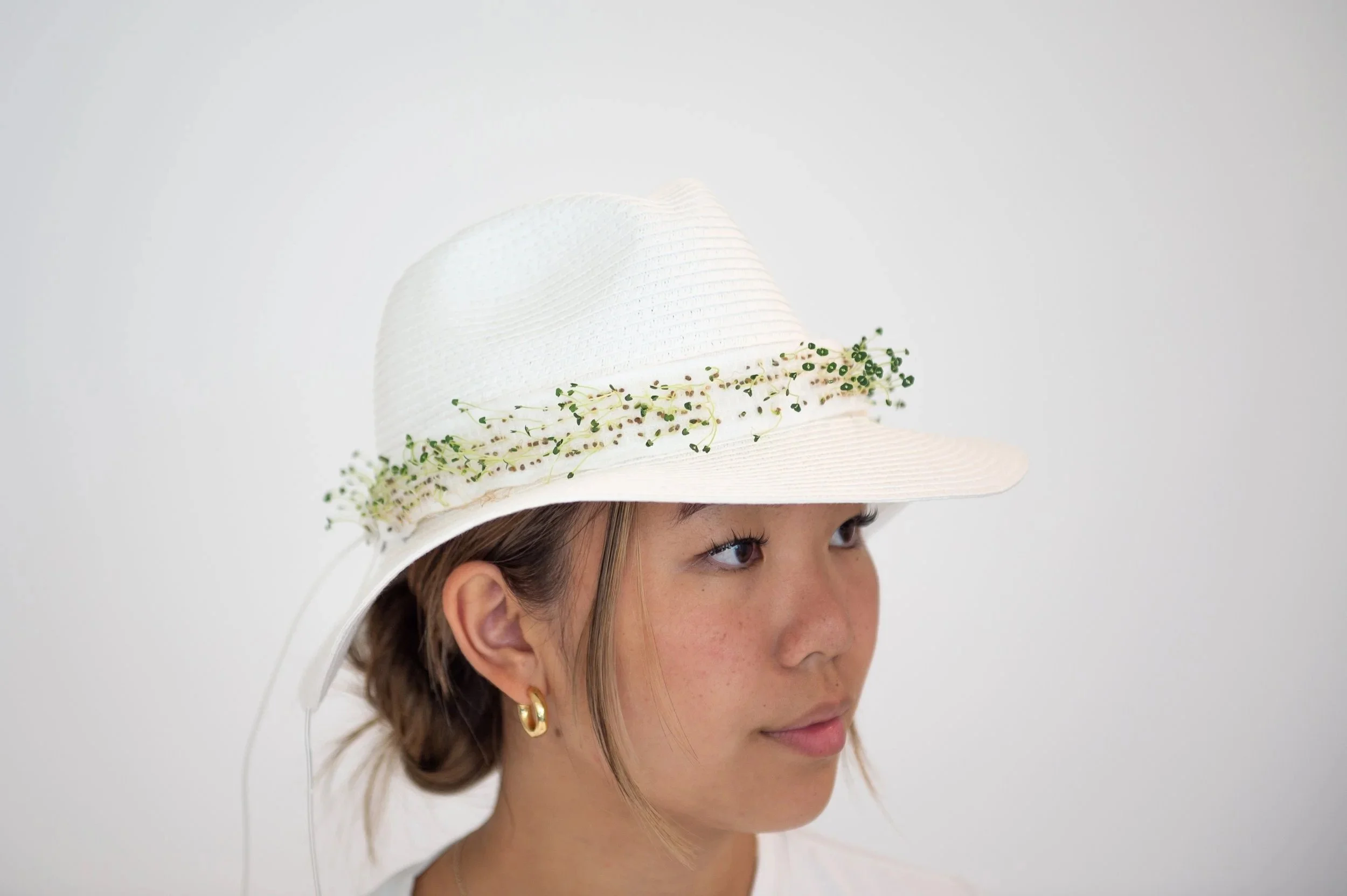
Self-caring hat: We made a waffle-weave hatband that helps the wearer care for the chia seeds growing on it. The top layer holds the seed-integrated yarns, while the bottom layer contains a thin tube with tiny holes that release water. Connected to a small peristaltic pump, this built-in irrigation system automatically waters the sprouts throughout the day, making it ideal for sunny outdoor use without manual watering.
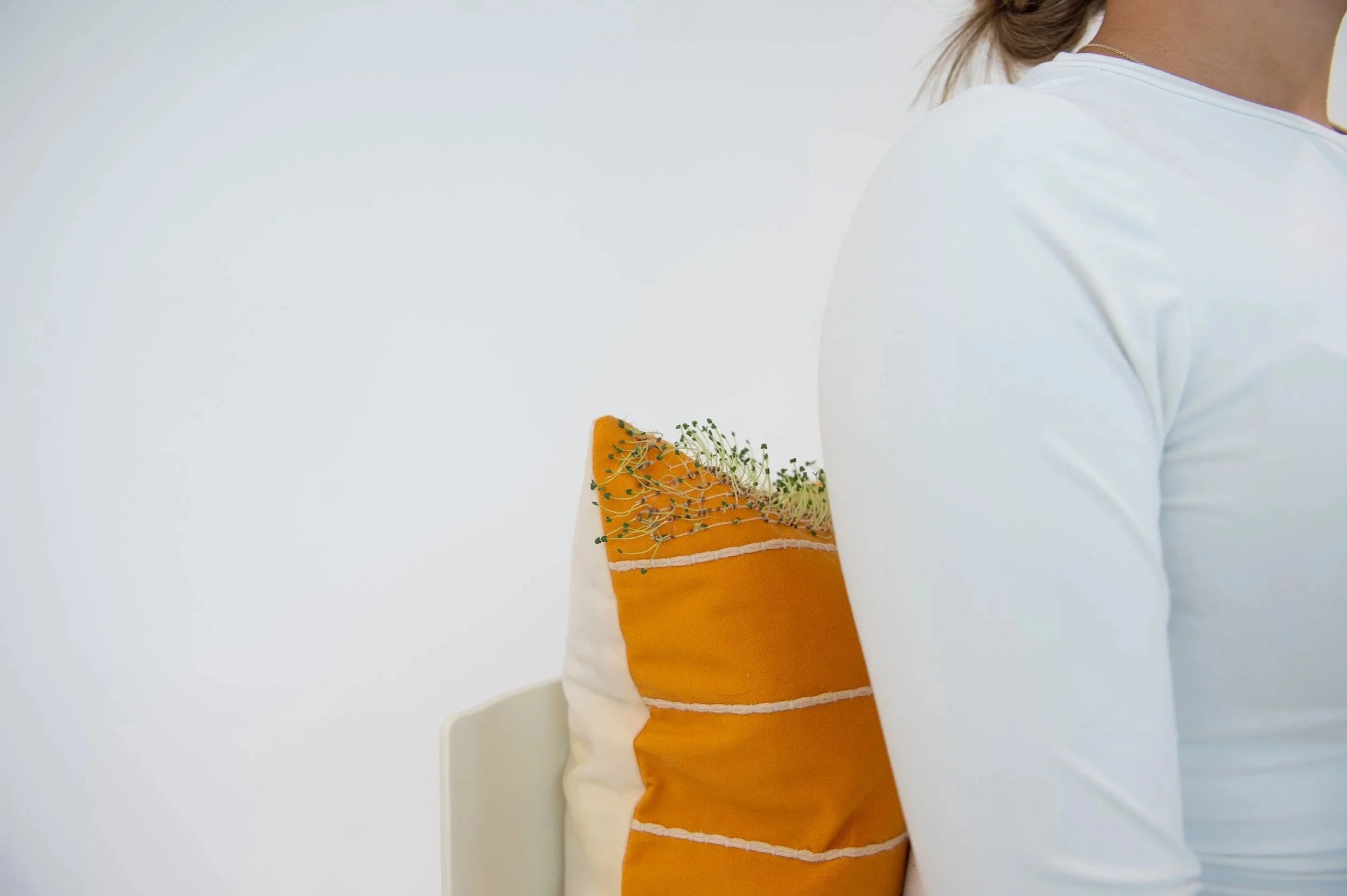
Indoor garden throw pillow: This example shows how seed-integrated hydrogel yarns can be used in upholstery by blending two home decor elements, throw pillows and houseplants, into one design. Using a substrate lining technique, we couched the yarns onto a pre-made pillowcase, attaching them only on the top surface so the chia sprouts will not be squished when someone leans against the pillow.
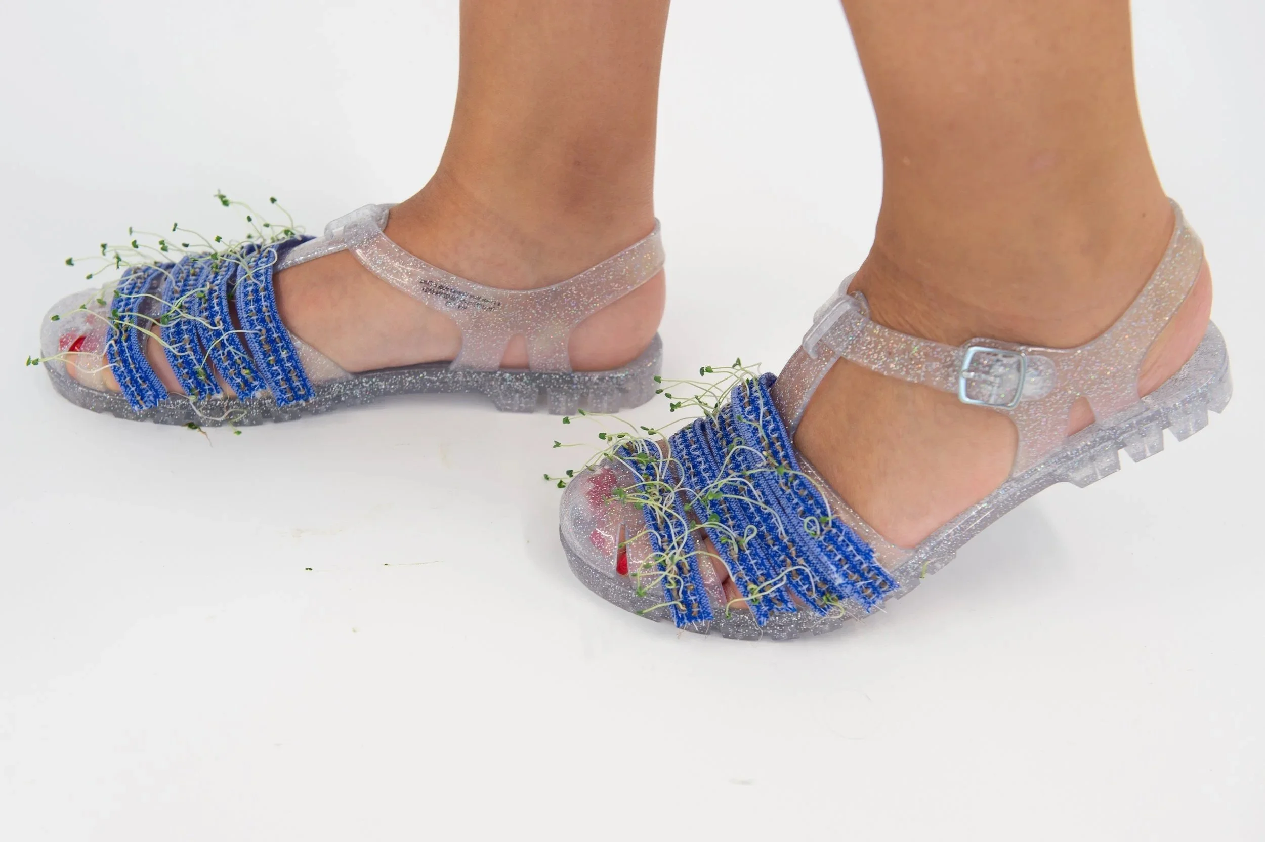
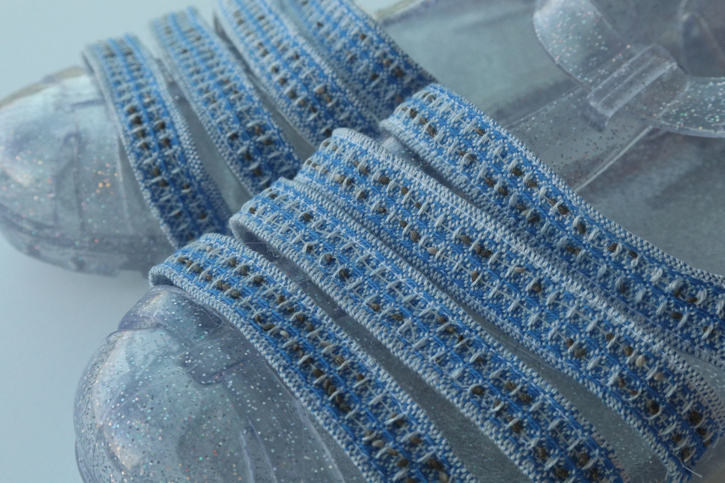
Outdoor activity encouraging sandals: This application uses a hybrid layering approach to integrate seed-integrated hydrogel yarns. We wove the seeds into the top layer using a double-weave structure, while the bottom waffle-weave layer supports the roots and helps retain moisture. The woven piece can be attached directly to jelly sandals, which can handle the moisture needed for sprouting.
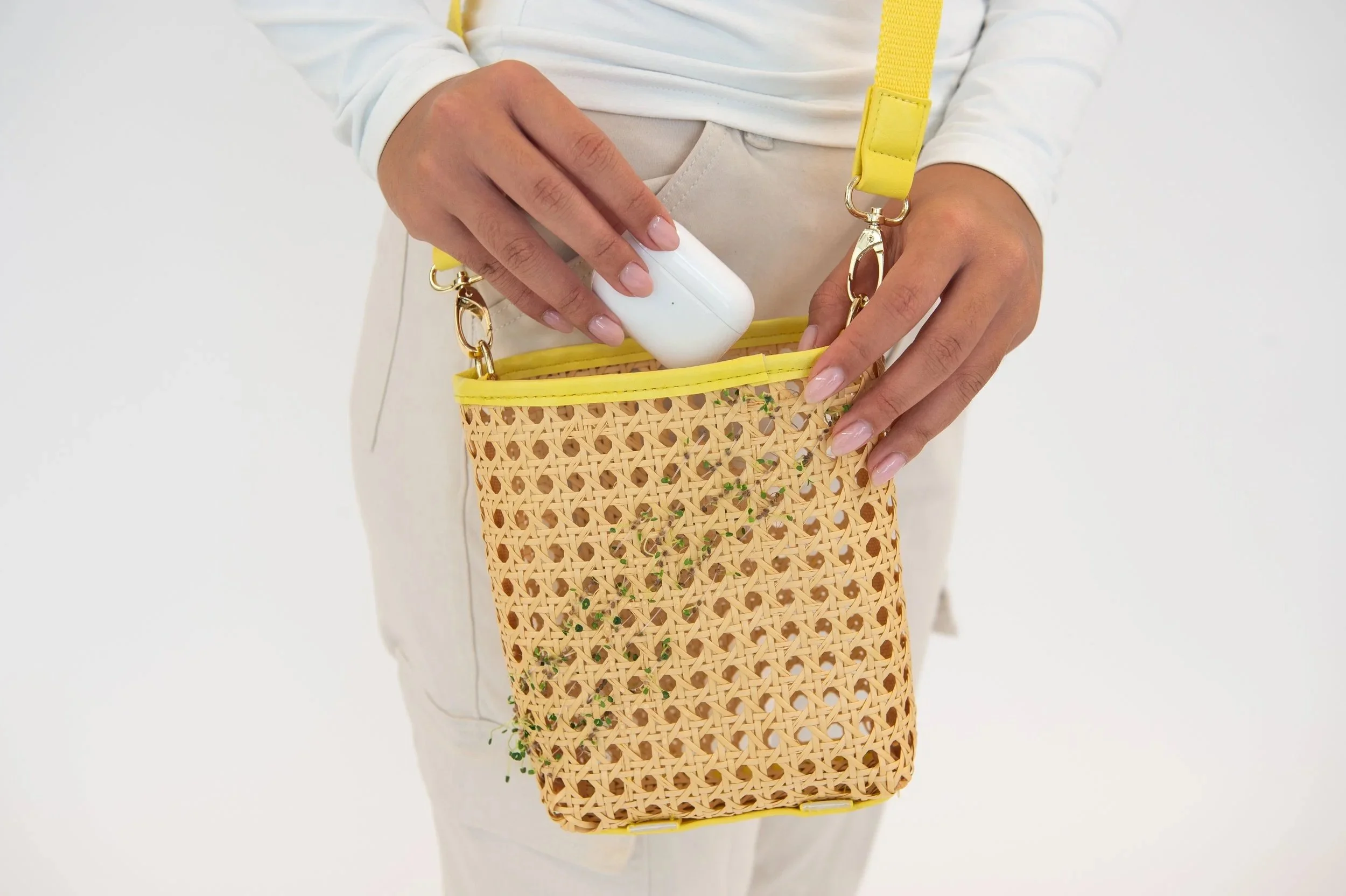
Rattan woven bag: This application uses structural interlacing to add seed-integrated hydrogel yarns into a pre-made rattan bag using basketry techniques. The rattan’s open weave allows good airflow and space for roots to grow, but since it does not retain moisture, the sprouts need frequent watering, or a water-retaining insert can be added.
Acknowledgement
This tutorial is based on the LivingLoom project, created at the Hybrid Body Lab at Cornell University, directed by Prof. Cindy Hsin-Liu Kao.
LivingLoom Research Team: Jingwen Zhu (Lead Researcher), Samantha Chang, Ruth Zhao, Prof. Cindy Hsin-Liu Kao (Lab Director)
Publication: Jingwen Zhu, Samantha Chang, Ruth Zhao, and Cindy Hsin-Liu Kao. 2025. LivingLoom: Investigating Human-Plant Symbiosis Through Integrating Living Plants Into (E-)Textiles. In Proceedings of the 2025 CHI Conference on Human Factors in Computing Systems (CHI '25). Association for Computing Machinery, New York, NY, USA, Article 773, 1–18. https://doi.org/10.1145/3706598.3713156 (Best Paper Award)
The tutorial is prepared by Hybrid Body Lab members Jingwen Zhu, Samika Agarwal, Megan Wu, and Emily Fan, advised by Lab Director Prof. Cindy Hsin-Liu Kao.
Also available on Science Buddies
Isopropyl Alcohol (99-99.8%)
Isopropyl Alcohol (70%)
Formlabs Form3L Printer
Formlabs Clear Resin V4
Sandpaper (213Q P800-grit)
Aieenjor Water-Based Nail Polish
Nail Filer
X-acto Knife
UV Lamp
Nail Drill
SLA print the file of the nail design.
Carefully remove the 3D print from the build plate and soak in isopropyl alcohol (99-99.8%).
Cut the supports from the 3D print.
Once supports are removed, give a rinse in IPA for any remaining support debris.
Using super fine sandpaper (P800), sand all the 3D prints gently to remove any remnants of supports. If needed, you can take an X-acto knife and gently remove any little broken support pieces, but be careful not to cut the model itself.
Add 0.2 grams of red cabbage power to the water-based nail polish bottle.
Using a nail drill, mix the red cabbage power with the water-based nail polish.
Apply 8 layers of the pH nail polish to the nails. Wait for it to dry between each layer.
To test the color change under different pH conditions, prepare testing solutions at different pH levels. We used pH 4, 7, and 10 for this testing. Other alternative testing solutions include vinegar, bleach, water, and milk.
File the natural nails and the back of the nails with a nail filer.
Clean both the natural nails and the back of the nails with isopropyl alcohol (70%) and isopropyl alcohol (99-99.8%), respectively.
Apply a clear, double-sided adhesive nail sticker to the natural nail.
Attach the nails at a 45º angle from the nail bed to the nail tip.

Isopropyl Alcohol (99-99.8%)
Isopropyl Alcohol (70%)
Formlabs Form3L Printer
Formlabs Clear Resin V4
Sandpaper (213Q P800-grit)
ViniMay Metal Chrome Gel Nail Polish
Angelina nail supply Clear UV Top Coat
Nail Filer
X-acto Knife
UV Lamp
SLA print the file of the nail cover design.
Carefully remove the 3D print from the build plate and soak in isopropyl alcohol (99-99.8%).
Cut the supports from the 3D print.
Once supports are removed, give a rinse in IPA for any remaining support debris.
Using super fine sandpaper (P800), sand all the 3D prints gently to remove any remnants of supports. If needed, you can take an X-acto knife and gently remove any little broken support pieces, but be careful not to cut the model itself.
Apply 1 of the metal chrome nail polish to the nails. Cure with a UV lamp in between each layer.
Once dried, paint the nail cover with a clear UV top coat. Cure with a UV lamp.

Construct the controller circuit following the circuit schematic
It is recommended that the circuit be soldered onto a Perma-Proto Quarter-sized Breadboard PCB for easy use.
Optional: The controller PCB can be assembled inside a 3D-printed enclosure. The enclosure 3D file is attached. The enclosure can be printed either using a SLA printer or a FDM printer. The screws of the enclosure are M2-6 Socket Head Screws.
Connect the solenoid to the controller circuit.
Program the microcontroller through Arduino. The code can be downloaded below.
Power on the controller circuit either through a USB cable or using a tattoo machine power supply. The supply voltage should be 5V.
The solenoid should be activated in a linear actuation at a fast frequency. Turning the knob of the potentiometer, the speed of the solenoid would change: clockwise → faster speed; counterclockwise → slower speed. The indicator LED will also change color accordingly.
File the natural nail and the back of the nail cover with a nail filer.
Clean both the natural nail and the back of the nail cover with isopropyl alcohol (70%) and isopropyl alcohol (99-99.8%), respectively.
Apply a clear, double-sided adhesive nail sticker to the natural nail.
Attach the nail cover at a 45º angle from the nail tip to the nail bed.
Unstick the nail from left to right and remove the remaining sticker tab peeling it off with your fingers.


Isopropyl Alcohol (99-99.8%)
Isopropyl Alcohol (70%)
Formlabs Form3L Printer
Formlabs Clear Resin V4
Sandpaper (213Q P800-grit)
ViniMay Metal Chrome Gel Nail Polish
D&Z orange and turoquoise gel polish color 313 and 365
Dafu yellow gel polish color M045
Angelina nail supply Clear UV Top Coat
Nail File
X-acto Knife
UV Lamp
SLA print the two files of the ring and nail cover design.
Carefully remove the 3D print from the build plate and soak in isopropyl alcohol (99-99.8%).
Cut the supports from the 3D print.
Once supports are removed, give a rinse in IPA for any remaining support debris.
Using super fine sandpaper (P800), sand all the 3D prints gently to remove any remnants of supports. If needed, you can take an X-acto knife and gently remove any little broken support pieces, but be careful not to cut the model itself.
Apply one layer of the metal chrome gel nail polish to the nails. Cure with a UV lamp in between each layer.
Apply 3 layers of yellow, orange and turquoise gel nail polish to the nails. Make gradient of colors using a fluffy brush. Cure with a UV lamp in between each layer.
Once dried, paint the nail cover with a clear UV top coat. Cure with a UV lamp.

Construct the controller circuit following the circuit schematic.
It is recommended that the circuit be soldered onto a Perma-Proto Quarter-sized Breadboard PCB for easy use.
Program the microcontroller through Arduino. The testing code can be downloaded below.
When talking to the microphone, the on-board LED will dim according to the volume of the sound.
To visualize the sound, program the microcontroller through Arduino. The code can be downloaded below.
To connect the Arduino to the p5.js visualization, p5 serial control need to be installed: https://github.com/p5-serial/p5.serialcontrol
The p5.js visualization sketch: link

Construct the controller circuit following the circuit schematic.
It is recommended that the circuit be soldered onto a Perma-Proto Quarter-sized Breadboard PCB for easy use.
Program the microcontroller through CircuitPython. The testing code can be downloaded below.
To prepare the audio file, prepare the sound file in .wav format using the online recording tool: https://resonaterecordings.com/voice-recorder/
The .wav file needs to be renamed to “audio.wav” and saved to the CircuitPython folder when the microcontroller is connected to the computer.
File the natural nail and the back of the nail cover with a nail filer.
Clean both the natural nail and the back of the nail cover with isopropyl alcohol (70%) and isopropyl alcohol (99-99.8%), respectively.
Apply a clear, double-sided adhesive nail sticker to the natural nail.
Attach the nail at a 45º angle from the nail bed to the nail tip.
Unstick the nail from left to right and remove the remaining sticker tab peeling it off with your fingers.

Isopropyl Alcohol (99-99.8%)
Isopropyl Alcohol (70%)
Formlabs Form3L Printer
Formlabs Clear Resin V4
Sandpaper (213Q P800-grit)
Born Pretty Red Jelly Gel Nail Polish
Angelina nail supply Clear UV Top Coat
Nail Filer
X-acto Knife
SLA print the file of the nail cover design.
Carefully remove the 3D print from the build plate and soak in isopropyl alcohol (99-99.8%).
Cut the supports from the 3D print.
Once supports are removed, give a rinse in IPA for any remaining support debris.
Using super fine sandpaper (P800), sand all the 3D prints gently to remove any remnants of supports. If needed, you can take an X-acto knife and gently remove any little broken support pieces, but be careful not to cut the model itself.
Apply 2 layers of Born Pretty Red Jelly Gel nail polish to the nails. Cure with a UV lamp in between each layer.
Once dried, paint the nail cover with a clear UV top coat. Cure with a UV lamp.
Solder five laser diodes to each battery connector. The red wire connects to “SW,” and the blue wire connects to “-”.
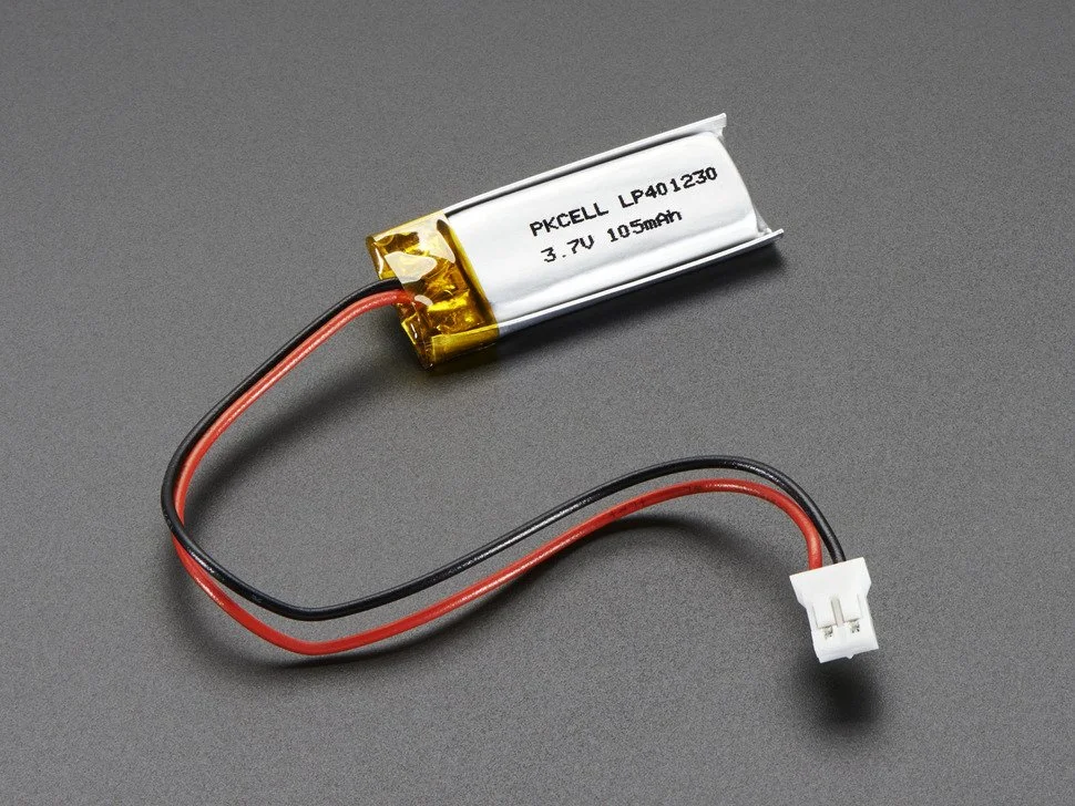
Connect 3.7V LiPo batteries to each of the battery connectors.
Before switching on the battery connector, ensure that the laser diode is not pointing at human eyes or camera lenses. Safety goggles are recommended.
File the natural nail and the back of the nail cover with a nail filer.
Clean both the natural nails and the back of the nails with isopropyl alcohol (70%) and isopropyl alcohol (99-99.8%), respectively.
Apply a clear, double-sided adhesive nail sticker to the natural nail.
Attach the nail cover at a 45º angle from the nail bed to the nail tip.

Isopropyl Alcohol (99-99.8%)
Isopropyl Alcohol (70%)
Formlabs Form3L Printer
Formlabs Clear Resin V4
Sandpaper (213Q P800-grit)
D&Z Black Gel Polish
Angelina nail supply Clear UV Top Coat
X-acto Knife
UV Lamp
SLA print the file of the necklace design.
Carefully remove the 3D print from the build plate and soak in isopropyl alcohol (99-99.8%).
Cut the supports from the 3D print.
Once supports are removed, give a rinse in IPA for any remaining support debris.
Using super fine sandpaper (P800), sand all the 3D prints gently to remove any remnants of supports. If needed, you can take an X-acto knife and gently remove any little broken support pieces, but be careful not to cut the model itself.
Apply two layers of the D&Z Black Gel Polish to the words of the necklace. Cure with a UV lamp in between each layer. After applying the final coat, cure with a UV lamp again.
Once dried, apply a clear UV top coat to the words of the necklace. Cure with a UV lamp.
Layout SkinLink modules inside each slot on the necklace, and adjust the placement accordingly to avoid bending the flexible connectors
Measure the length between each component, and prepare the SkinLink wiring connectors accordingly.
Program the SkinLink in Arduino. The code can be downloaded below.
One day in the future humans might be able to see in the dark without having to turn on a flashlight or wear night-vision goggles. In the meantime, with the aid and versatility of SkinLink, we have AutoLight: A hands-free wearable eyebrow mount that uses an ambient light sensor to turn on automatically in low-light.
Autolight is made up of a SkinLink MCU module, an ambient light sensing module, and a white neopixel LED module as well as elastic resin printed housings for the skin link module, light sensor, and LED.
Aesthetically inspired by the Borg from Star Trek, it boasts a rather conspicuous cyberpunk aesthetic, in hopes to push humans further toward an augmented future with new abilities.
Elastic 50A Formlabs resin tank
SkinLink MCU module
Ambient Light Sensing Module
Neopixel RGB LED Module
Create a design with structures that accommodate the SkinLink MCU module, Ambient Light Sensing Module, and Neopixel RGB LED Module
Open the .stl in PreForm and print it on a Formlabs From 3 printer in clear resin
Soak in isopropanol alcohol bath after print
Color the prints with acrylic paint to match the desired skin tone
Layout SkinLink modules on face, adjust the placement accordingly to avoid bending the flexible connectors
Program SkinLink in Arduino
Attach the MCU module with DUO eyelash glue
Attach the cover for the MCU with DUO eyelash glue
Attach the housing of sensor and LED modules with DUO eyelash glue
Insert sensor and LED module into their corresponding housings
Insert the battery onto the battery connector on MCU module, tuck the battery behind the ear
Pain relief envisioned as something you could wear while going out at night. Current heating patches are squares or ovals. ThermalDermal proposes any one-line shape as the substrate for heat. In the example below, it is pictured as a “hot tramp stamp”. A wearable patch that is both physically and conceptually hot.
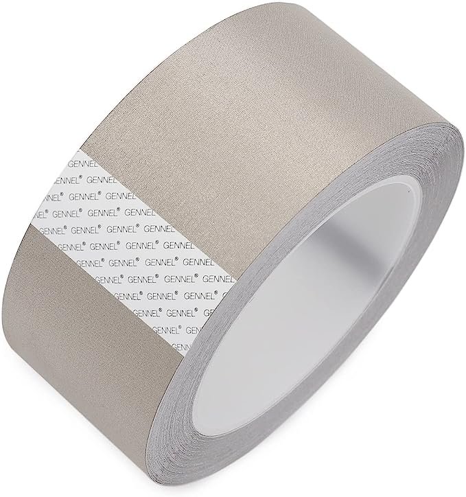
Gennel conductive cloth fabric adhesive tape
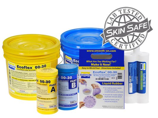
Ecoflex silicone 00-30
Thermochromic pigment
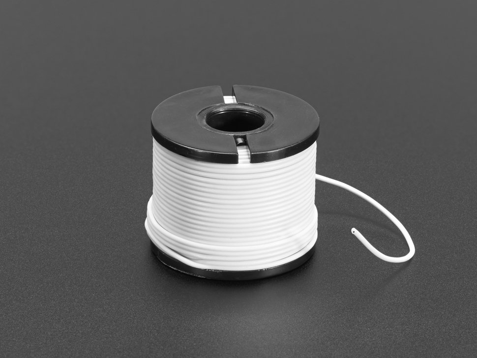
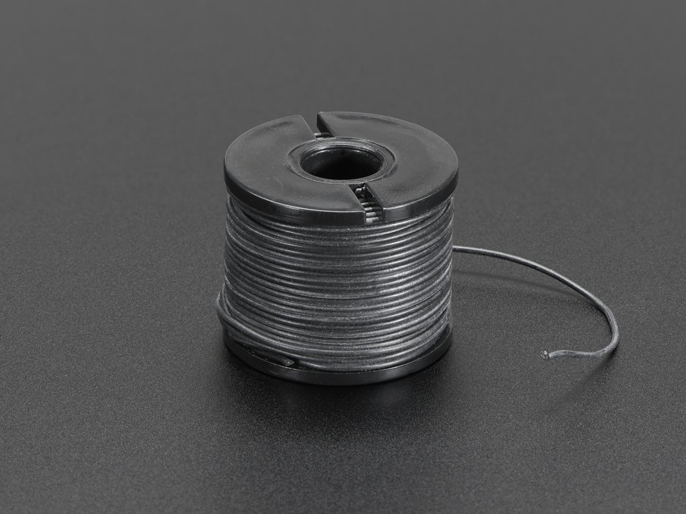
Silicone Cover Stranded-Core Wire - 50ft 30AWG White
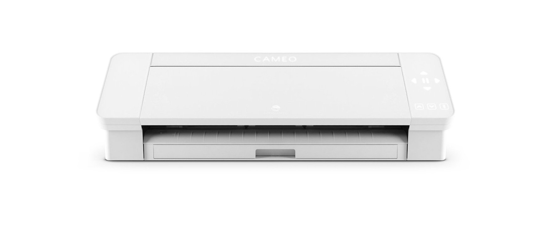
Vinyl cutter
Xacto blade or box cutter
Create a 4mm thickness of one-liner 2D design, avoid any intersections
Import the design into Silhouette, vinyl cut it on conductive fabric tape
Remove the negative area of the tape
Measure the resistance of the trace, ideal resistance is around 10 ohms.
Solder wires onto each end of the trace
Mix 5 grams of part A and 5 grams of part B of Ecoflex
Add 0.5 grams of thermochromic pigments
Place the vinyl cut tape on a flat surface, pour the silicone mixture onto the vinyl cut tape to achieve an even layer
After the silicone fully cures, flip it and cut out the shape with a Xacto knife
Microporous tape layered across to create desired thickness
Layered uline tape over to desired thickness
Place tattoo on top right side facing out and cut tape layers to fit tattoo
Stick to skin or plastic backing to store
Imagining current wearables less as something to hide and more as something to flaunt and show off. Hearing aids typically tuck discreetly behind the ear for minimal visibility. This project rests in front of the ear, proudly showing off its audacious sculptural and material form.
It mimics a common tattoo motif of an angel whispering in an ear, but doubles as a functional object, amplifying sound. The angel is literally whispering!
Formlabs clear resin
Hearing Aid
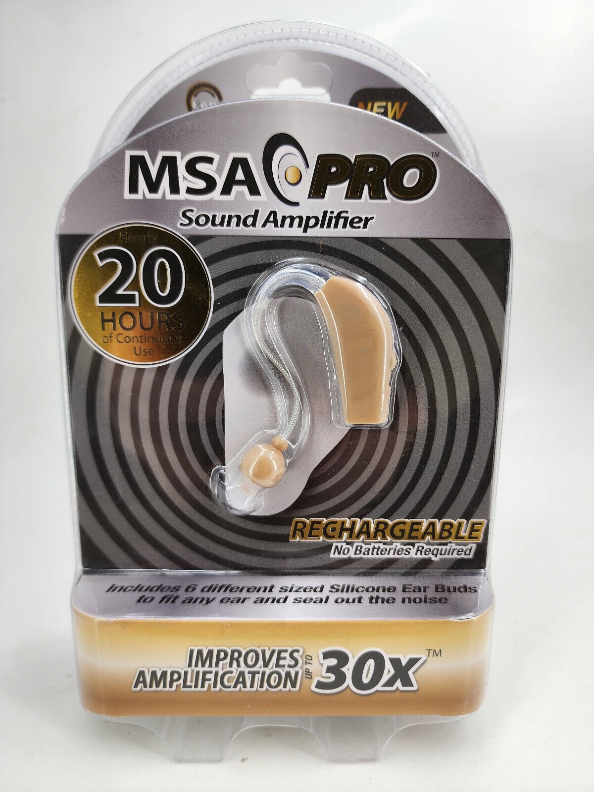

disassemble the hearing aid using a screwdriver
Apply hot glue around the wire connection to PCB
Download an ear 3D model
Pose a human mesh around it
Use a boolean to remove the shape of the ear from the model
Use another boolean to accommodate the PCB of the hearing aid
Export .stl file
Open the .stl in PreForm and print it on a Formlabs From 3 printer in clear resin
Soak in isopropyl alcohol bath after print
Insert the hearing aid PCB into the 3D print
Apply dots of hot glue onto non-essential areas


Picturing the surface of the human body as no different from that of a car or personal computer. In the future there might be an increasing need to cool embedded implants. Using 3D printed elastic resin, real PC fans are “installed” onto the surface of skin.
Elastic 50A Formlabs elastic resin tank
Fan
Battery
Switch connector
Wires
Silicone Cover Stranded-Core Wire - 50ft 30AWG White
Silicone Cover Stranded-Core Wire - 50ft 30AWG Black
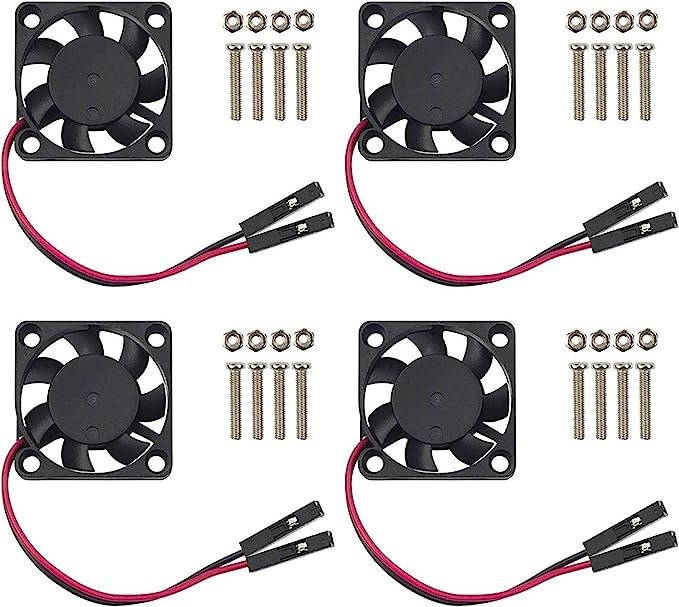


Open the .stl in PreForm and print it on a Formlabs Form 3 printer in elastic 50A resin
Soak in isopropyl alcohol bath after print
Desolder wires on the fan, solder silicone-coated stranded wire to the fan, note the polarity: white for + and black for -
Fitting soldered fans into the 3D print
Feed the wires through the channels in the 3D print
Solder the wires to the battery connector, white wires -> SW, black wires -> GND
Clean with alcohol swab as needed
Use DUO eyelash glue to apply the CoolingUnit on skin


UV Scale is a set of flexible resin printed scales that will visually change color under UV light. The scales are to be applied on the skin using a safe skin adhesive in a pattern which emulates a snake's skin as it basks in the sunlight. The pattern of snake skin is an irregular sort of tessellation that easily and naturally warps with the unusual geometry of the human body.
Elastic 50A Formlabs resin tank
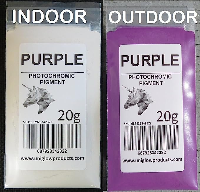
Photochromic pigment
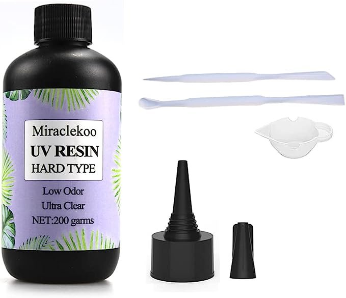
UV Resin soft type
DUO eyelash glue


Convert .svg file of scale 2D design to mesh in Blender
Extrude the plane to desired thickness
Export as .stl file
Open the .stl in PreForm and print it on Formlabs From 3 printer in elastic 50A resin
Mix 1 gram of purple photochromic pigment into 5 grams of UV resin soft type
Apply the mixture on the edges of each scale piece with a paintbrush
Curing under a UV lamp for 2 minutes
Apply DUO eyelash glue onto the bottom of each piece, wait for it to turn tacky and apply them onto skin.


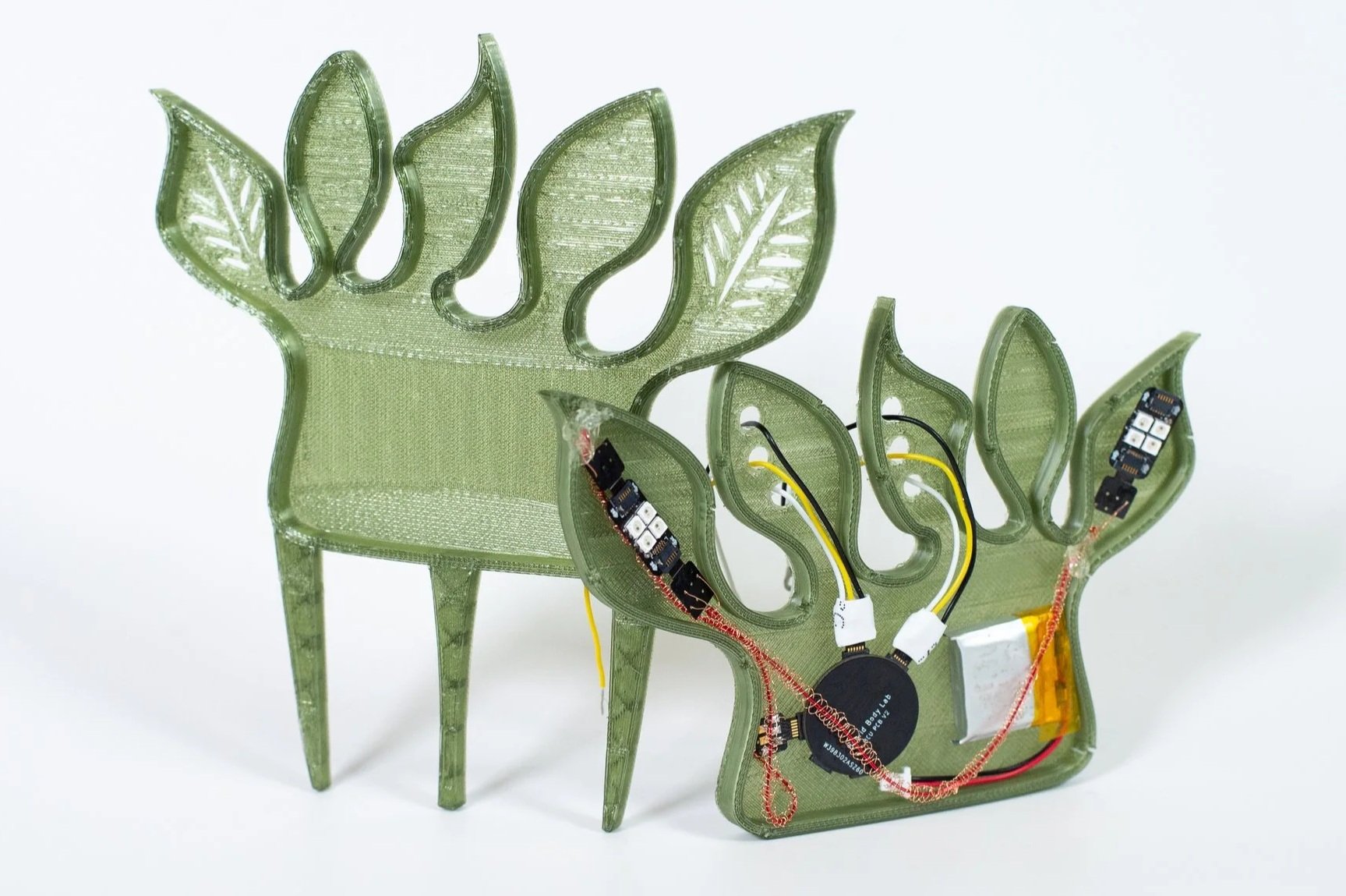
Social Prosthesis is a moving appendage designed as two headpieces made from rigid and soft structures. The soft skin of the prosthesis curls and contracts when triggered by touch on the face.
Social Prosthesis is made up of 3D resin print, silicone skin, and an embedded shape memory alloy circuit attached to a Duoskin capacitive touch.
Referencing the definition of prosthetic sociality, written by Mimi Thi Nguyen in the 2003 essay Queer Cyborgs and New Mutants, Social Prosthesis is an exploration of how technologies enhancing the human body create meanings that extend past the merging of biological and artificial—that must contest with the social and political contexts of its time.
EcoFlex NearClear 00-45
Shape Memory Alloy Spring, 0.5cm(5mm) coil diameter , 0.15 wire diameter, Pitch: wire size x2, transition temp 45C
Mold for silicone casting
Isopropyl Alcohol 99% - 99.8%
Resin printer
Korea Crystal Tec Transparent Stretchy Beading Line String 0.5 (or any thin, stretchy elastic to hold the nosepiece in place)
Sandpaper (3M Wetordry 213Q P800-grit)
Silicone Pigment (optional—for coloring silicone)
Alcohol Ink (optional—for coloring resin)
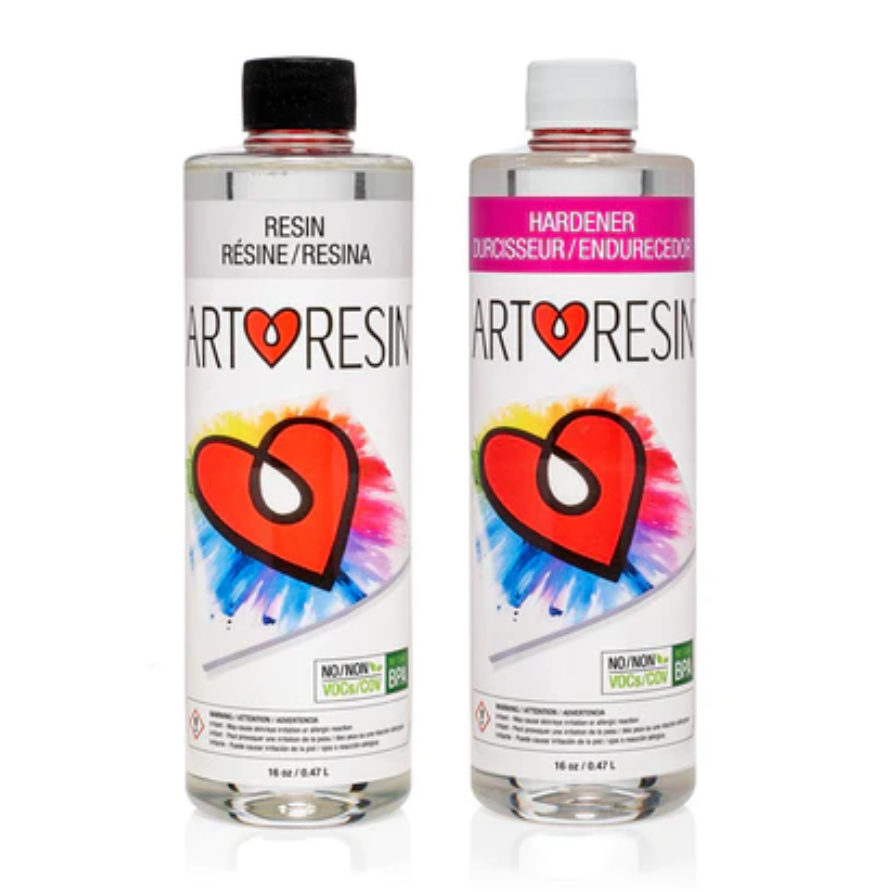
Art Resin (optional—for glossing resin)
32 AWG Copper Wires
15k Resistor
SOT23 Breakout Board (as perf board)
Multimeter
Optional: Isopropyl Mysristate


Resin Print
1. SLA print the two files of the Social Prosthesis design.
2. Carefully remove the 3D print from the build plate and soak in isopropyl alcohol (99-99.8%)
3. Cut the supports from the 3D print. The design has delicate and thin details, so it is important to remove the supports to determine that you are not cutting parts of the model.
4. Once supports are removed, give a rinse in IPA for any remaining support debris.
5. Using super fine sandpaper (P800), sand all the 3D prints gently to remove any remnants of supports. If needed, you can take an X-acto knife and gently remove any little broken support pieces, but be careful not to cut the model itself.
1. If you want to color the resin at this step, you can take alcohol ink and dilute it using isopropyl alcohol to achieve the desired opacity. Then, taking a paintbrush, coat the resin structures with the alcohol ink mixture. The resin will absorb the alcohol ink.
2. If you would like to gloss the resin at this step, take Art Resin and mix equal parts resin (black cap) and hardener (white cap) in a I1:1 ratio in a separate container with a disposable popsicle stick or paintbrush. Be sure to replace the caps correctly on the bottles when complete.
3. Using a (disposable) paintbrush, lightly coat the Art Resin on the resin print surfaces that require gloss. Allow to dry for at least 24 hours.
NOTE: Avoid putting the Art Resin on the surfaces that you want to stick to the face, to avoid creating a slippery surface for makeup application.

Circuit Schematic
1. Construct circuit following the circuit schematic
2. Crimp the ends of the SMA before silicone casting, in preparation to be soldered to the circuit.
1. Using a multimeter, test both ends of the SMA to ensure conductivity.
2. Using a DC power supply, you can test the curling of the silicone to ensure that it is moving as desired.
3. To reset: wait until SMA has cooled, and then manually stretch the SMA back to its maximum length.
1. Power the circuit with LiPo battery
2. Turn on switch on the Gemma M0, onboard LED shows yellow
3. Touch temporary tattoo, onboard LED turns purple
4. SMA should start shrinking
5. Wait for 45 seconds
6. SMA shrinking stops, onboard LED turns cyan

Silicone casting with purple color
1. Measure approximately 8g of Part A and approximately 8g of Part B of Ecoflex Near Clear 00-45.
2. Mix the two equal parts thoroughly using a popsicle stick.
OPTIONAL: to color the silicone, drop a pinprick of silicone dye into the clear mixture and mix. If you are trying to make a clear-colored gradient, create a separate silicone mixture with a colored dye.
4. Place into degassing chamber for 10 min to remove any air bubbles
5. Place SMA spring into mold and arrange to be cast into the silicone
6. Pour carefully into the mold, covering the SMA. Make sure the ends of the SMA are uncovered
7. Use a mixing stick or other tool to pop any extra air bubbles
8. Let cure for 4 hours.
9. When cured, carefully remove the silicone from the mold.

Skin Application
1. To apply the headpiece, you can take 3rd Degree and mix a pea-sized amount of Part A and B to create a silicone adhesive for the skin.
2. Once mixed, apply a thick layer to the back of headpiece on the areas that will contact the forehead
3. Press the headpiece with the silicone adhesive to the forehead and hold for 1 minute to let the product cure.
4. Gently test to make sure the headpiece is adhered to the skin. It will not be a super tight hold, but effective enough to hold up the piece securely while also easy to remove after.
5. To apply the nosepiece, hold the nose bridge of the piece to the nose (as if putting on glasses). Use the elastic band to secure in place.
6. The circuit should also be lifted to hide behind the head.
1. Gently peel the piece off, and remove the silicone adhesive from the back of the headpiece. It should come off in one piece.
2. Use isopropyl Myristate to remove any extra residue
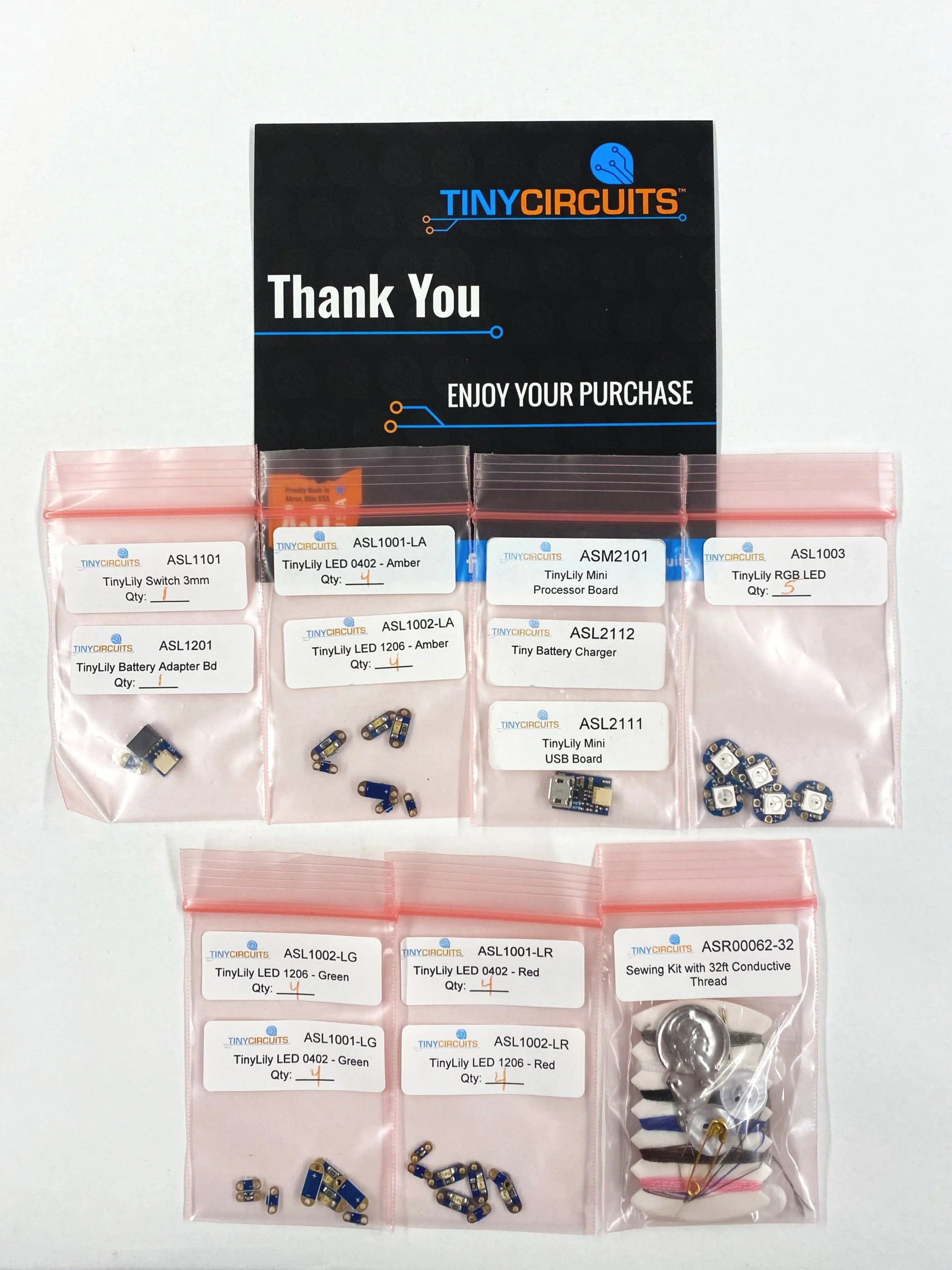
TinyLily Kit
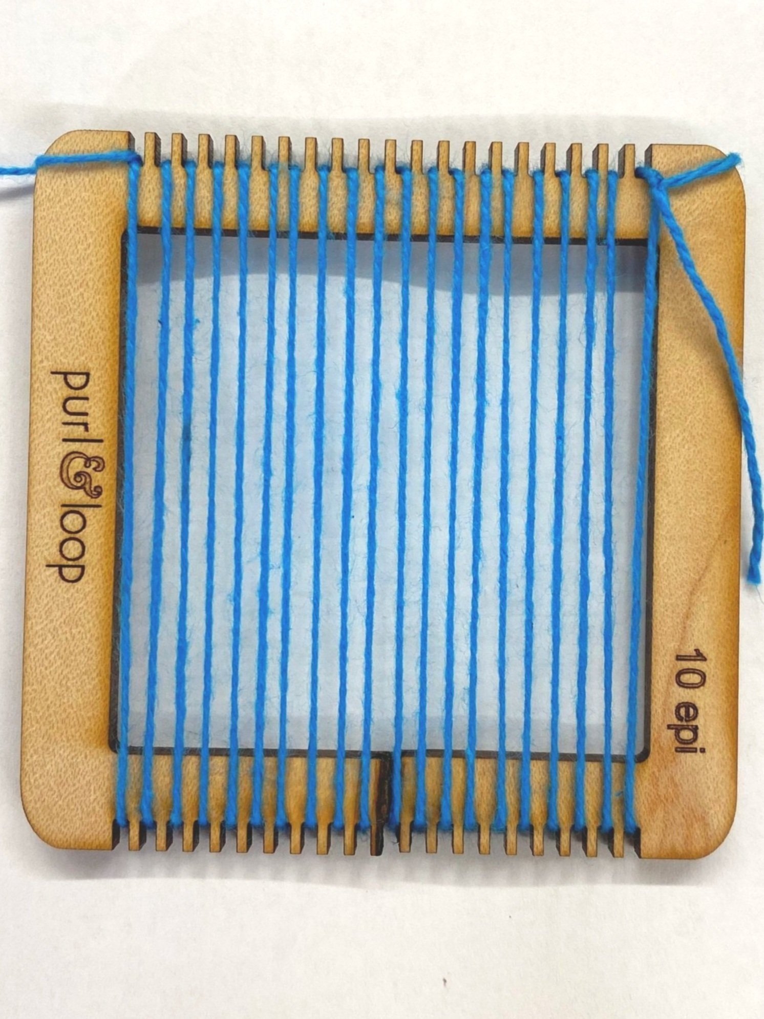
Loom (20 slots or 10 e.p.i)
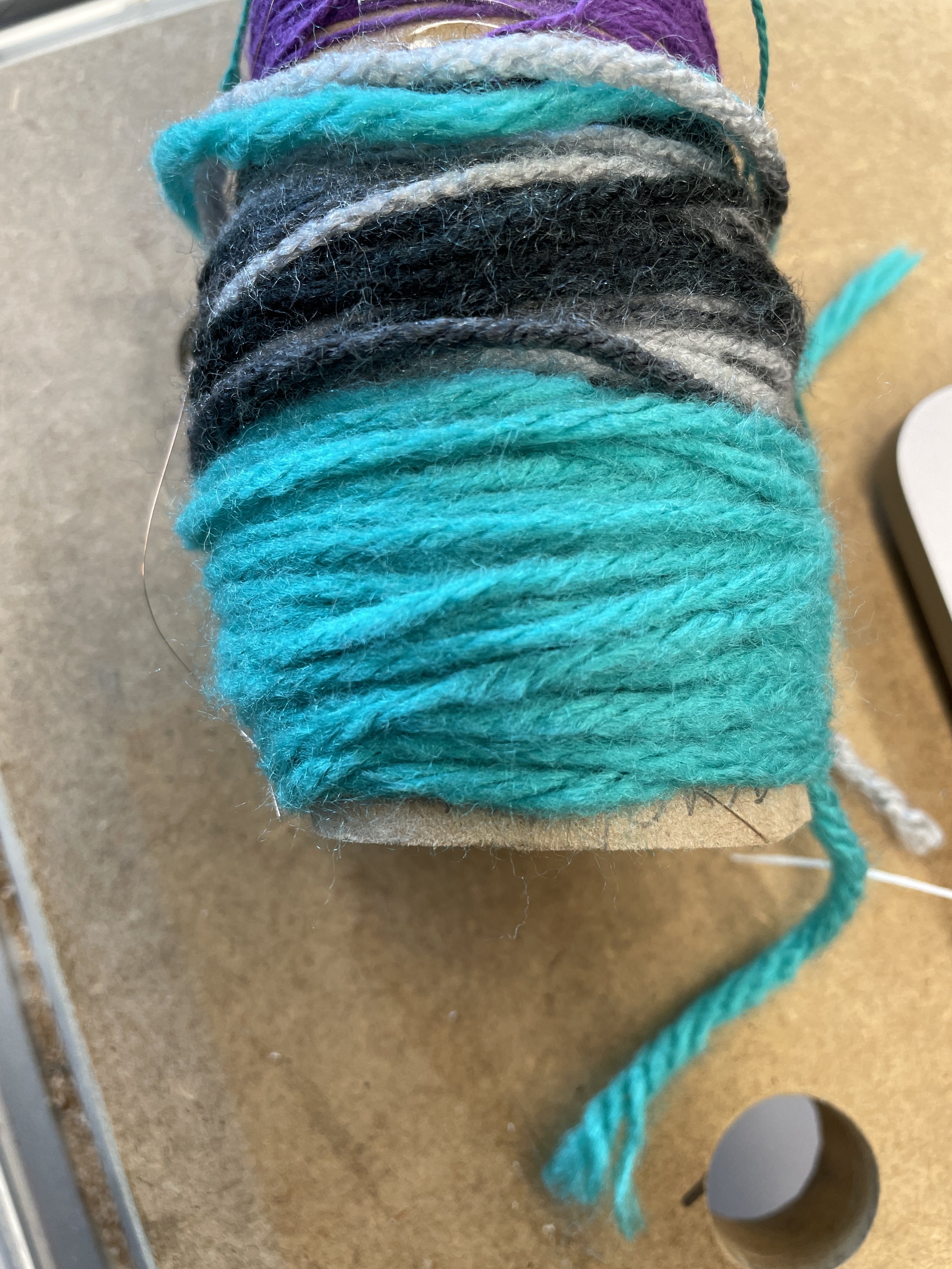
Cotton yarn (Recommended: 20 warp threads, 6.5 yards of thread)
Acrylic yarn (chunkier than cotton)
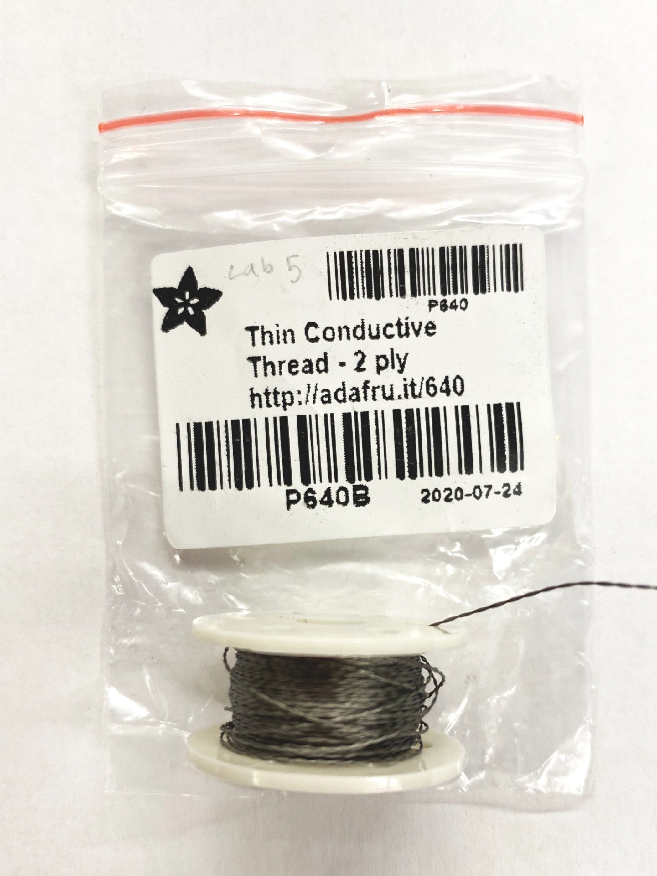
Conductive thread
Scissors
Comb
Multimeter (how to use)


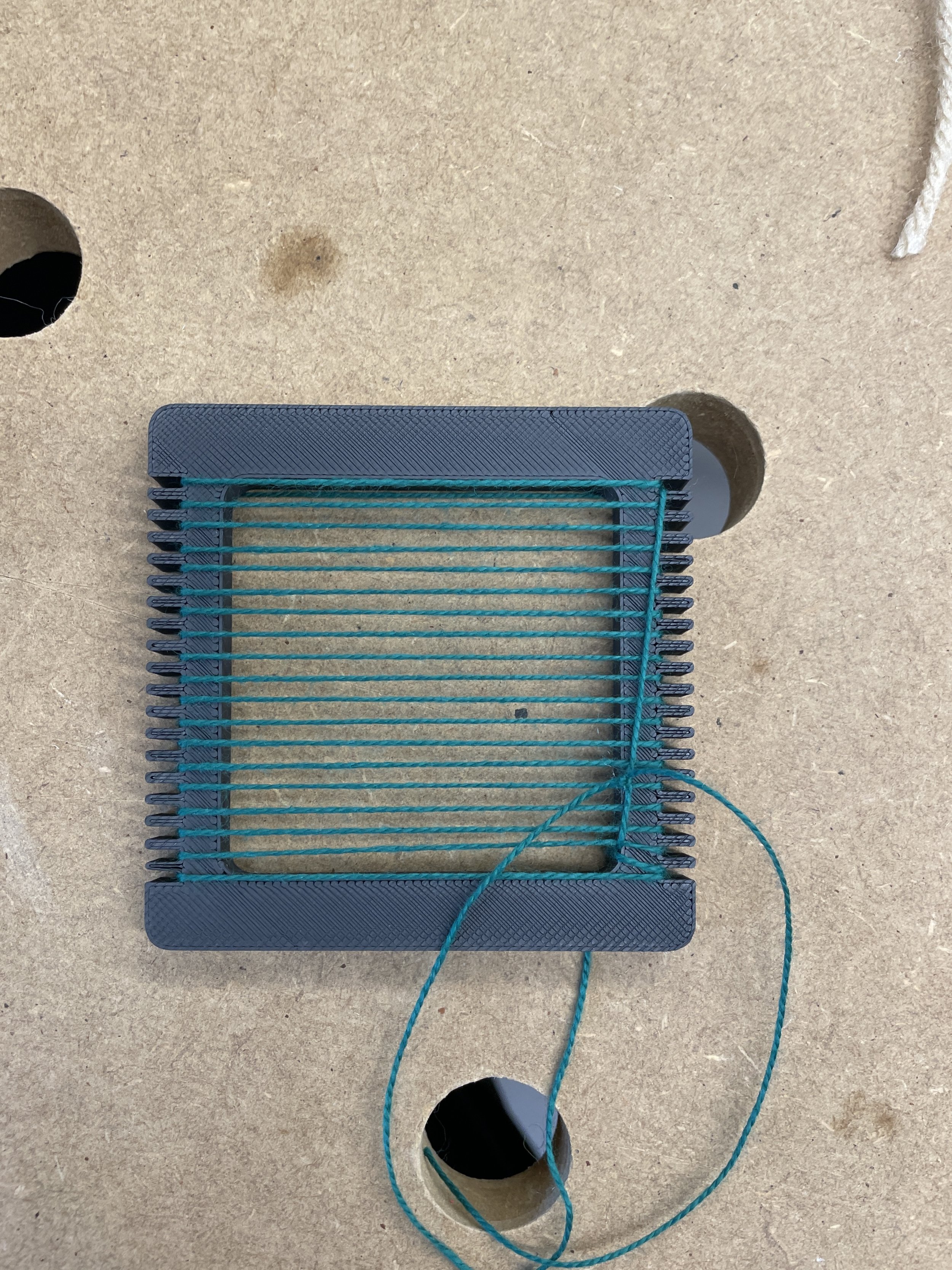


Woven fabric is formed by interlacing warp yarns and weft yarns, which run in perpendicular directions. The warp yarns are vertical, and held under tension on a loom, while weft yarns are horizontal and pass between warp yarns.
First, try setting up the loom using the chunky acrylic yarn we have provided (the thickest yarn on the spool). Follow the instructions below to get familiar with weaving a plain weave.
Set up for weft
Measure out 6.5 yards of thread (we’ve measured it for you).
Pull your yarn through the whole in your “tapestry needle”. Your kit does not come with a tapestry needle, but you can tape the yarn to anything long and thin (ex. A paintbrush or toothpick). Leave a 3-4 inch tail. This is what we will use to weave the yarn between the warp threads.
Plain Weave
Plain weave is considered the most basic weaving structure. In plain-woven fabric, each weft yarn goes over one warp yarn and under the next. This "over, under" sequence is repeated. Neighboring weft yarns pass through warp yarns in alternating sequences to secure the structure.
Goal:
Start by following the instructions below to weave your first plain weave. Use the thicker acrylic yarn for this practice weave. You have an extra fine 20 slot loom, but you will only be using every other slot for the warp with this chunky yarn, so that you have 10 warp threads.

You will be constructing a basic plain weave with conductive thread to program using Arduino!
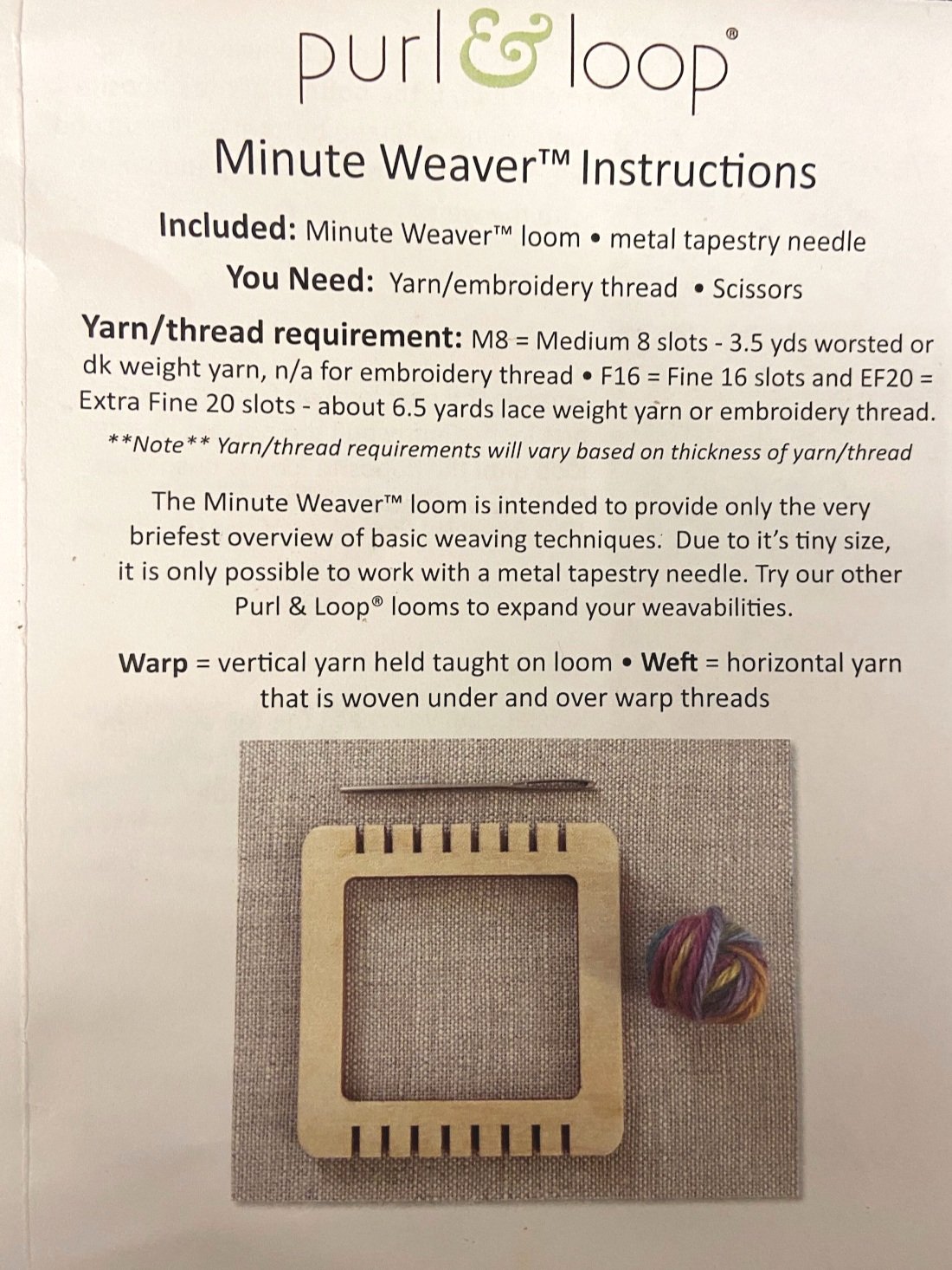
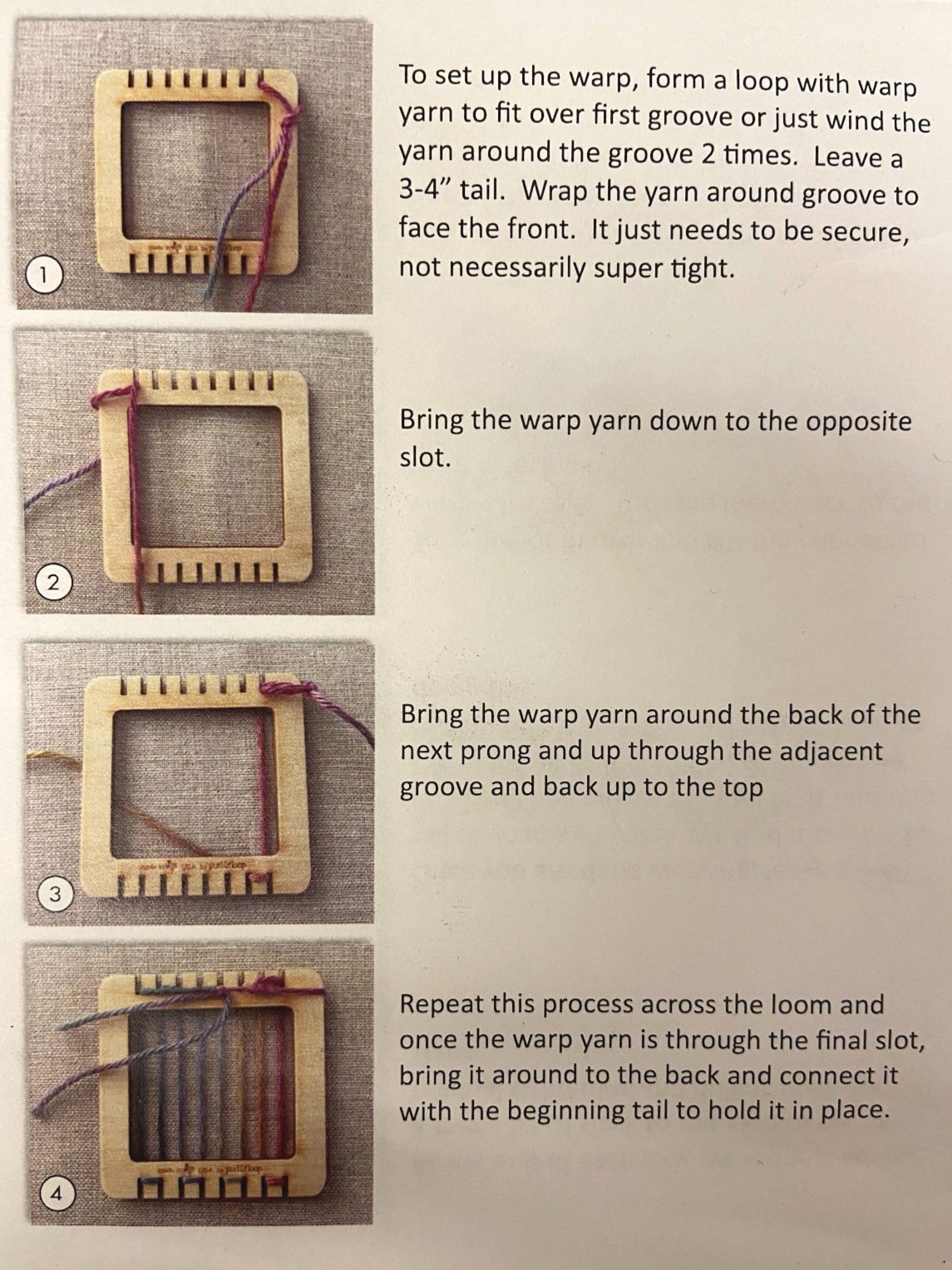
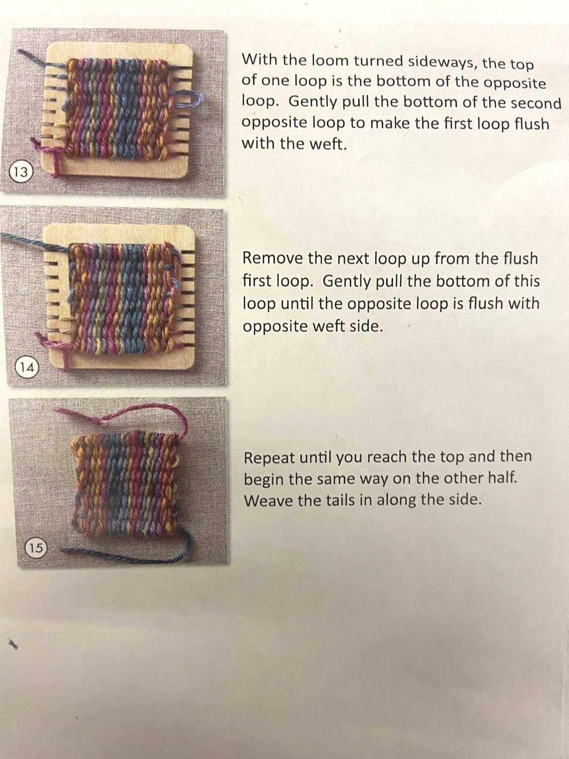
**Click to Enlarge Purl & Loop Instructions below

1. Set up loom warp with thin yarn. The one used in this tutorial is 20 warp threads, 6.5 yards of thread.
2. Start with a plain weave and weave about a third of the way up.
Note: It may be easier to have tails of the threads on alternating sides of the weft yarn so it is easier to hook up to the TinyLily Mini Processor (tails for conductive threads should stay on the same side for easier programming)
3. Cut off the yarn. Cut ~1.5 yards of conductive thread. Weave this continuously until you have at least a 0.5cm section of conductive thread.
4. Continue to plain weave with your yarn, weaving a 0.5cm section.
5. Repeat steps 3 and 4, two more times so that you have 3 evenly spaced sections of conductive thread the center of the weave.
6. Continue to plain weave until the loom is filled.
7. Finish your weave and remove it from the loom using steps 10-15 from pictures provided in the Purl & Loop tutorial. Feel free to reference videos.


Download Arduino and use this link for TinyLilyProcessor with Arduino for more details .
1. Connect your TinyLily to the computer
2. Launch the Arduino IDE and navigate to the Tools tab. For the TinyLily Mini Processor, we are going to make the following selections:
Board: "Arduino Pro or Pro Mini"
Processor: "ATmega328p (3.3V, 8MHz)"
Port: "COM##" - this is the port connected to the TinyLily via the MicroUSB cable (for Mac find “dev/cu.usbserial XXX”)
3. Upload the Captouch code we have provided for this tutorial to the TinyLily:
4. Connect the weave to the LilyTiny:
Conductive threads SHOULD NOT touch, cross or intersect each other
Make sure that the fraying from the ends of the conductive thread do not interfere with the processor or other conductive threads
5. Attach each conductive thread to pins A0, 2, and 3 by tying them to the holes in the TinyLily.
6. Observe the changing values in the serial monitor when you touch the conductive areas of your weave!
Observe the values changing with every touch!!
What other materials can we insert in the weft?
Colored thread
Thermochromic thread
How would you compare the capacitive touch slider you created here with the DuoSkin capacitive touch electrode in Lab 3?
Which step did you find most challenging in this lab?
For your Lab 5 submission, construct a woven slider (5.2). Post a photo onto the Canvas discussion board, with a 100-word description on what you made, responses to the reflection questions, and any challenges you encountered on the way.
Note: if you are already an experienced electronics builder you are encouraged to expand the project to match your skillset.
Q1. Between conductive thread and copper wire, which one would be more conductive and reliable?
Answer: Copper wire would be more conductive and often more reliable than conductive thread.
Q2. After weaving the conductive threads in the Tiny loom, in total 6 thread ends remain loose. Which ones get connected to which holes?
Answer: You have to connect three different conductive thread sections to three different pins of the TinyLily MCU. That means you can select one loose thread from each section and tie them to the assigned holes in the TinyLily. In our example, the TinyLily pins are A0, 2, and 3 respectively.
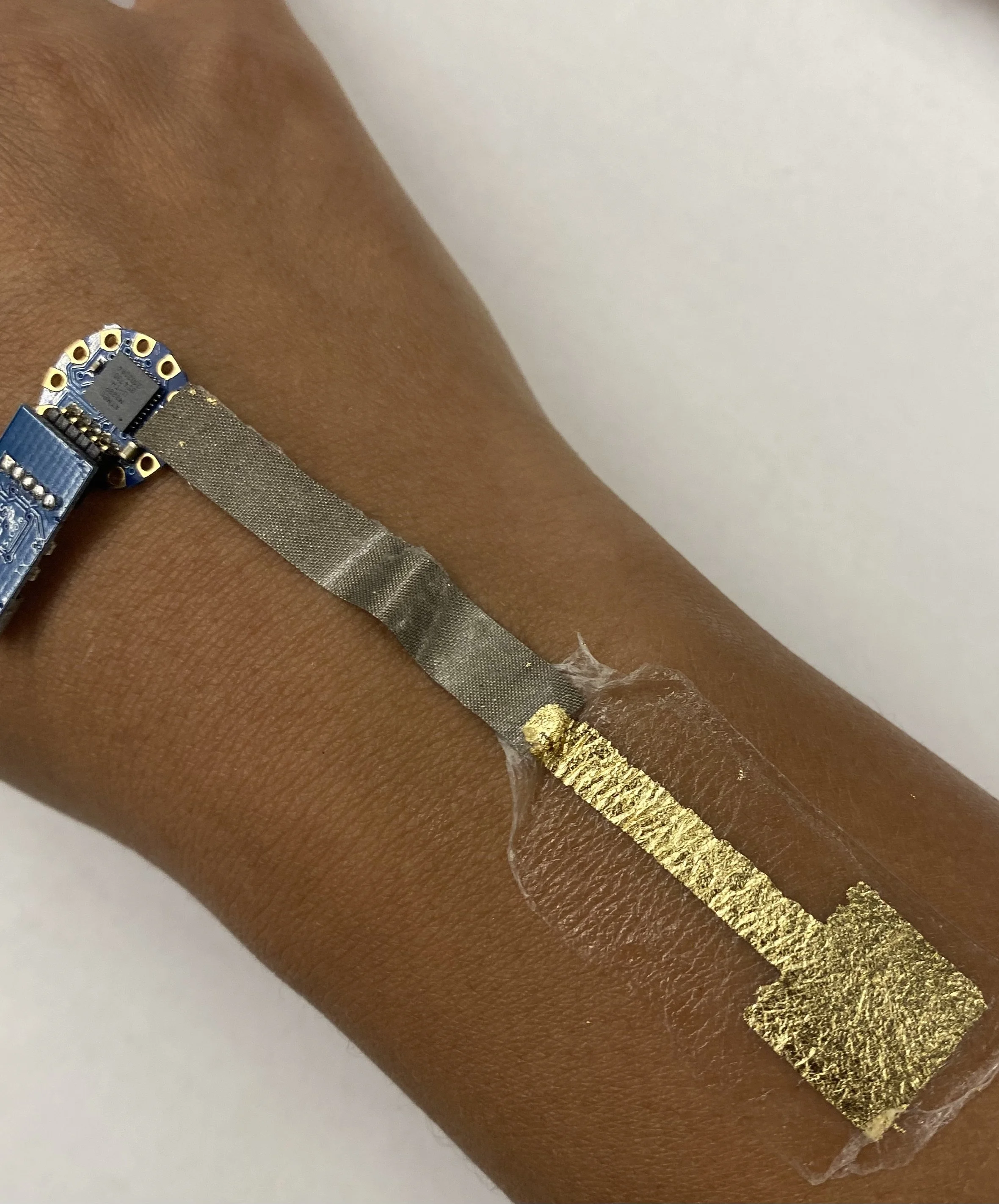
This is quite similar to Lab 3. In Lab 3, we made one capacitive sensing section with the gold metal and here we are making three capacitive sensing sections with three sections of woven conductive fabric.
36 Gauge Conductive Wire
Embroidery Hoop 6- inch
TinyLily starter Kit, incl. Mini Processor Board, USB Board, RGB LED, Battery Adaptor, Battery, needle, micro-USB cable
Temporary tattoo paper pack
PVA roll, Sulky (embroidery stabilizer)
Scissors
Sandpaper
Sponge or Tissues
Multimeter (How to use)


It may be helpful to follow this video tutorial of the entire process:
1. Construct the “SkinCloth” skin overlay substrate (this is described in Fig 2. In the SkinWire paper). Set to dry.
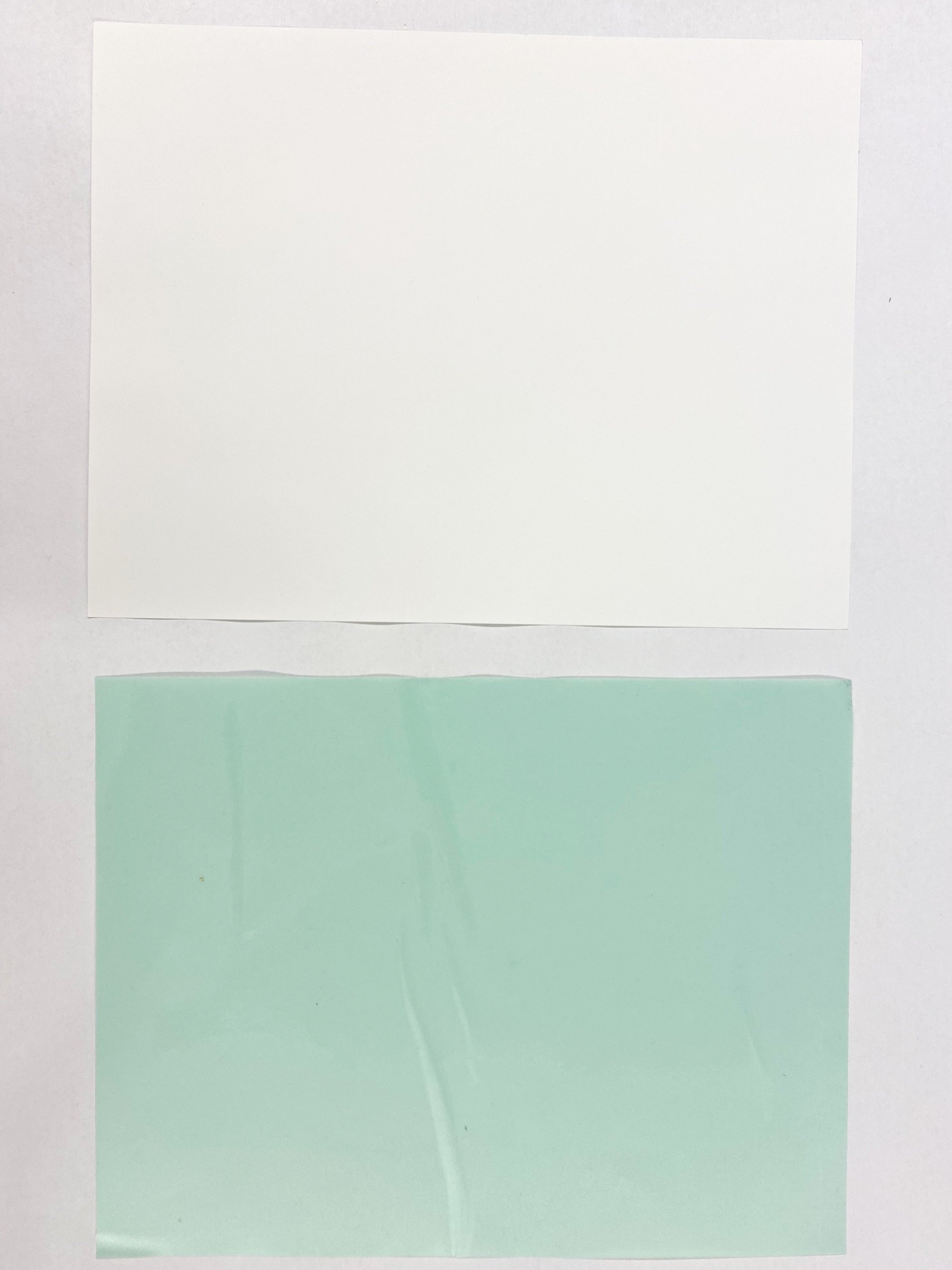
The three types of layer you will be using:
a. Green sheet: temp tattoo adhesive (packed together with the white sheet)
b. White sheet: temp tattoo silicone
c. Transparent sheet: PVA (Sulky, embroidery stabilizer)
The image bellow illustrates the three layers of SkinCloth
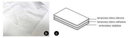
Three Layers of SkinCloth


2. Apply adhesive sheet on temp tattoo sheet
3. Remove the green backing from the adhesive layer
4. Stick that on temp tattoo sheet on the smooth and glossy silicon side of the white sheet.
5. Remove bubbles
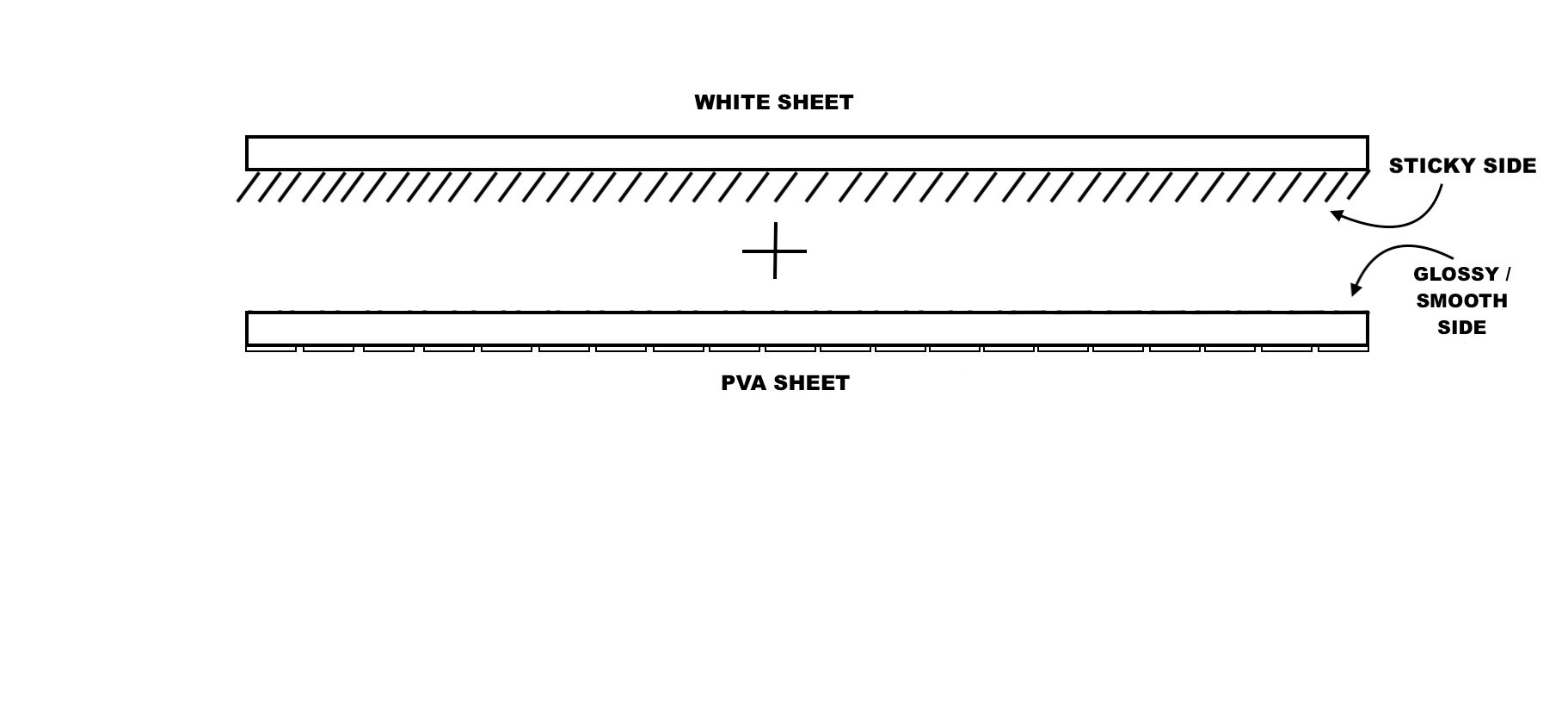
Diagram of application
6. Cut a piece of the PVA roll to fit the tattoo sheet. You can feel the PVA and observe that is has a smooth side and a rougher side. Set aside for now.
7. Remove the clear cover of adhesive paper. After you remove the adhesive, one side of will be papery, while the other is sticky.
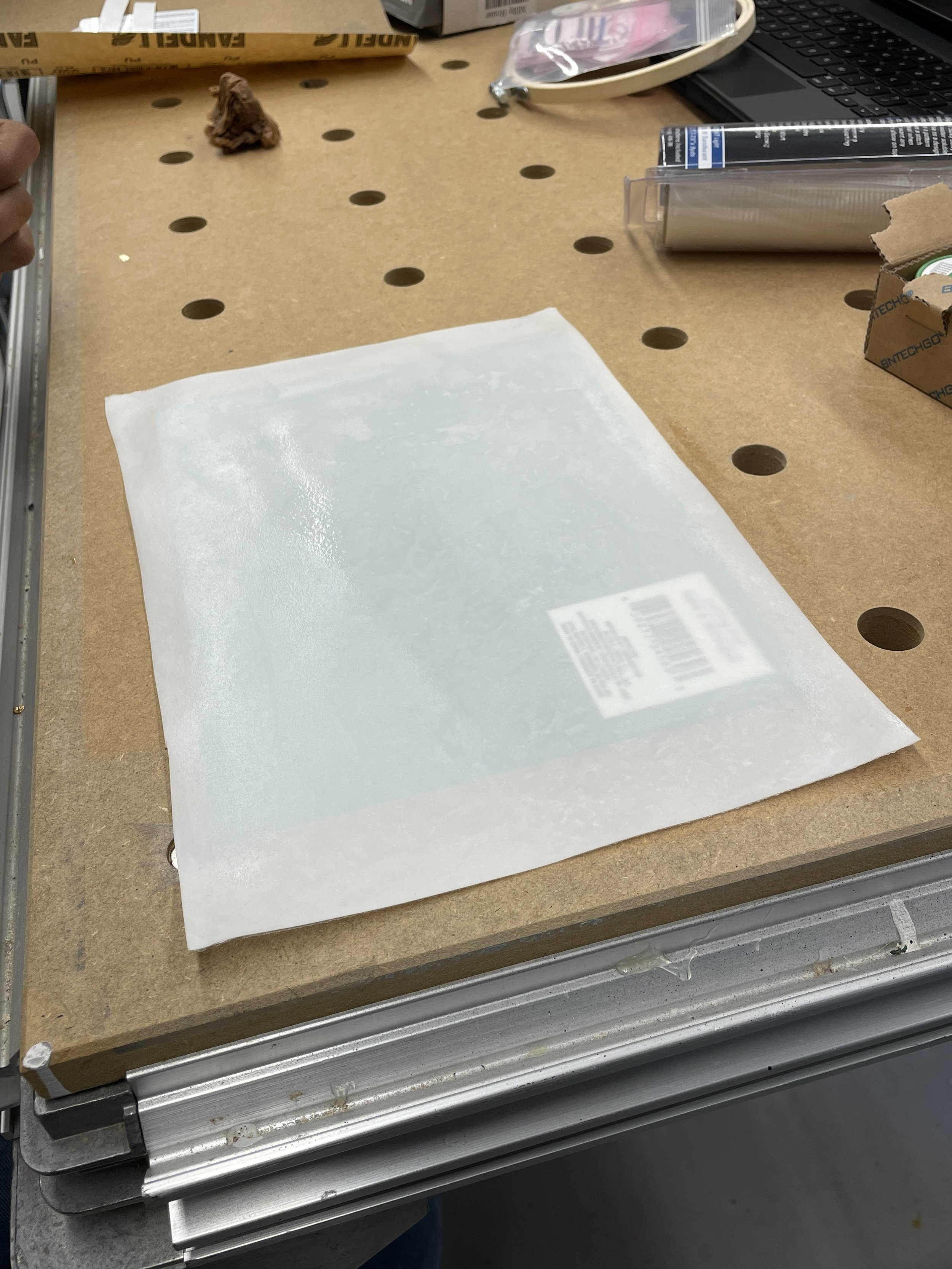
8. Stick the glossy (smooth) side of PVA onto the sticky side of the white sheet. So now one side is matte PVA and one side is paper.
It is recommended to put the PVA on the table first with the glossy side up, then gently place the white sheet with the sticky side facing down.
9. Remove paper part of temporary tattoo sheet by applying water
Soak the paper side with a wet paper towel/tissue or sponge (make sure not to apply TOO MUCH water!). The left picture below looks about right.
You can also tap it with your finger. Peel off the paper layer slowly and carefully. See the picture below right.
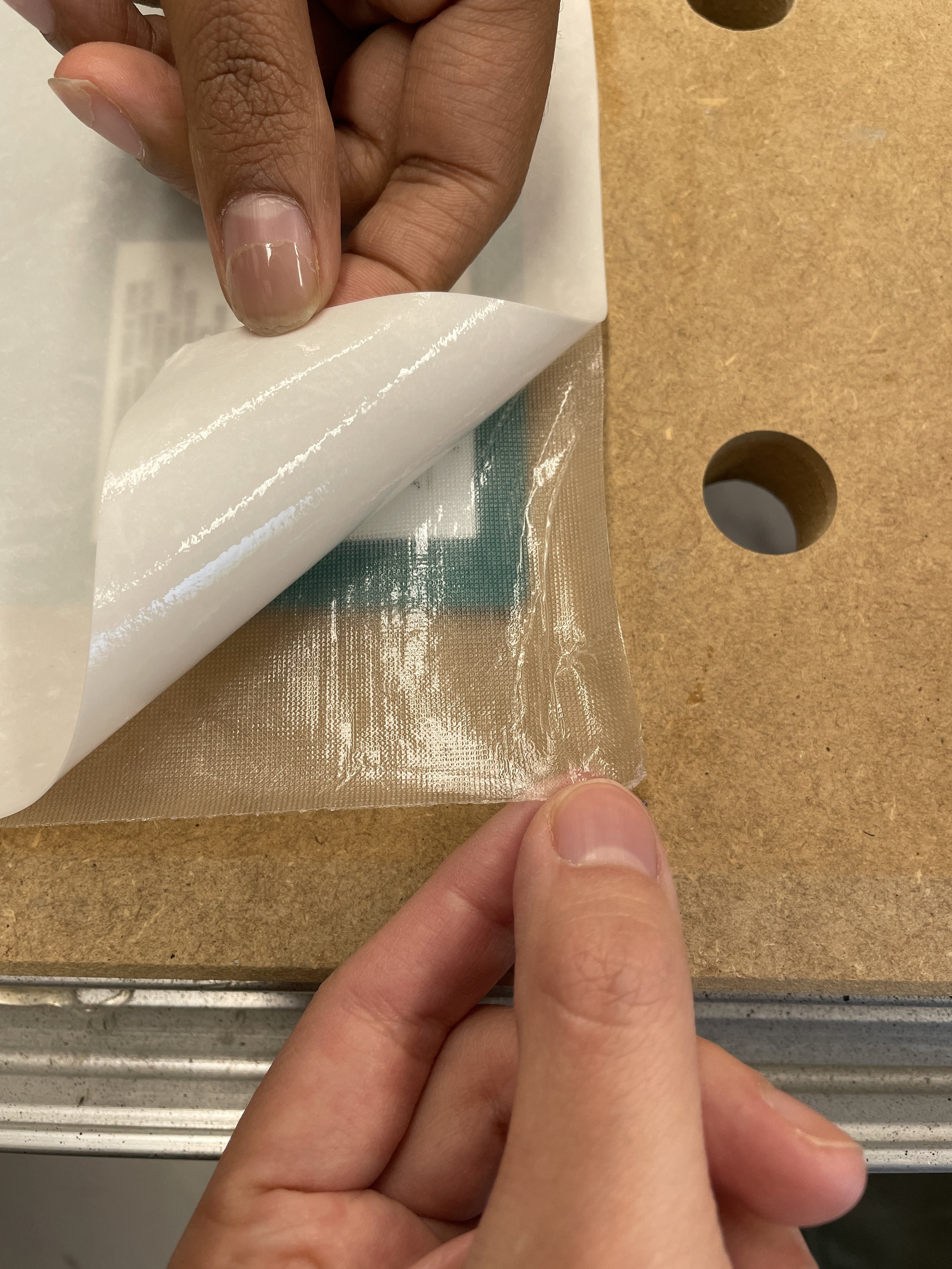
10. Wait for it to dry.


Detailed tutorial from TinyLily webpage. There are many ways the RGB LED can be connected in your project. For simplicity sake, we used the alligator clips here. Regardless of the method you choose, use the following steps to build your circuit.
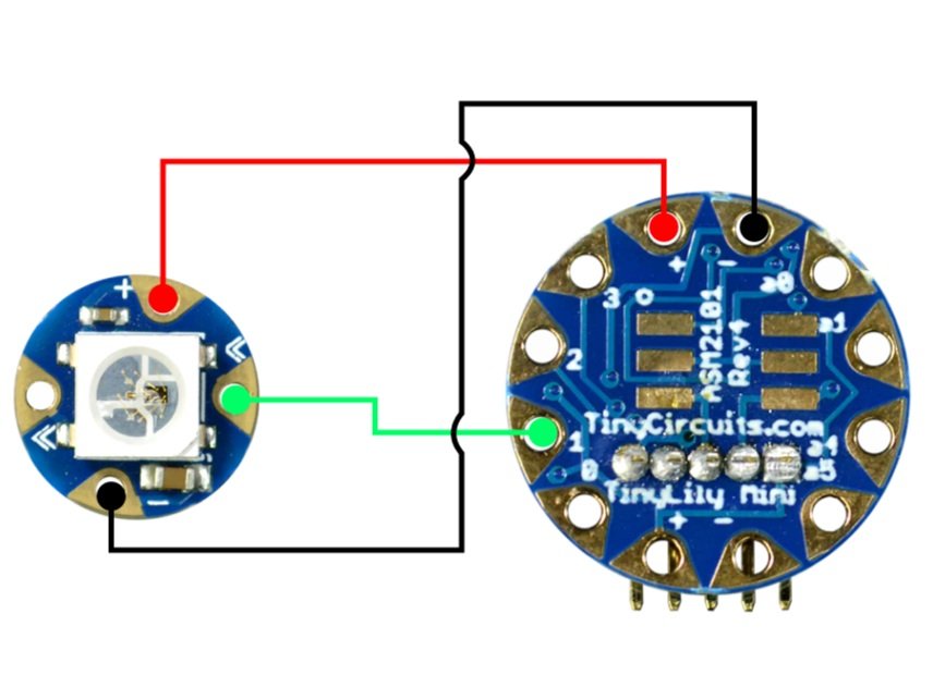
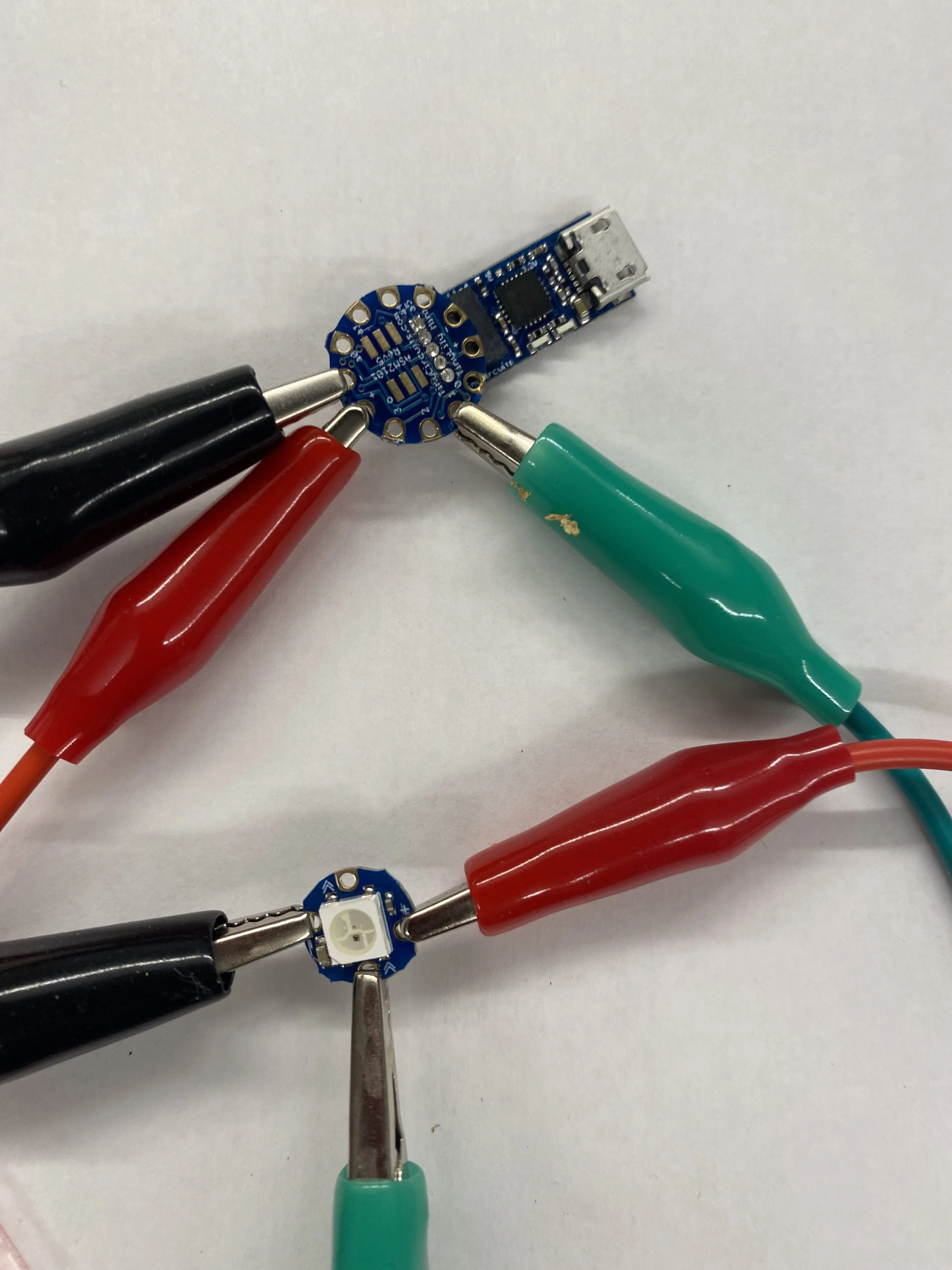
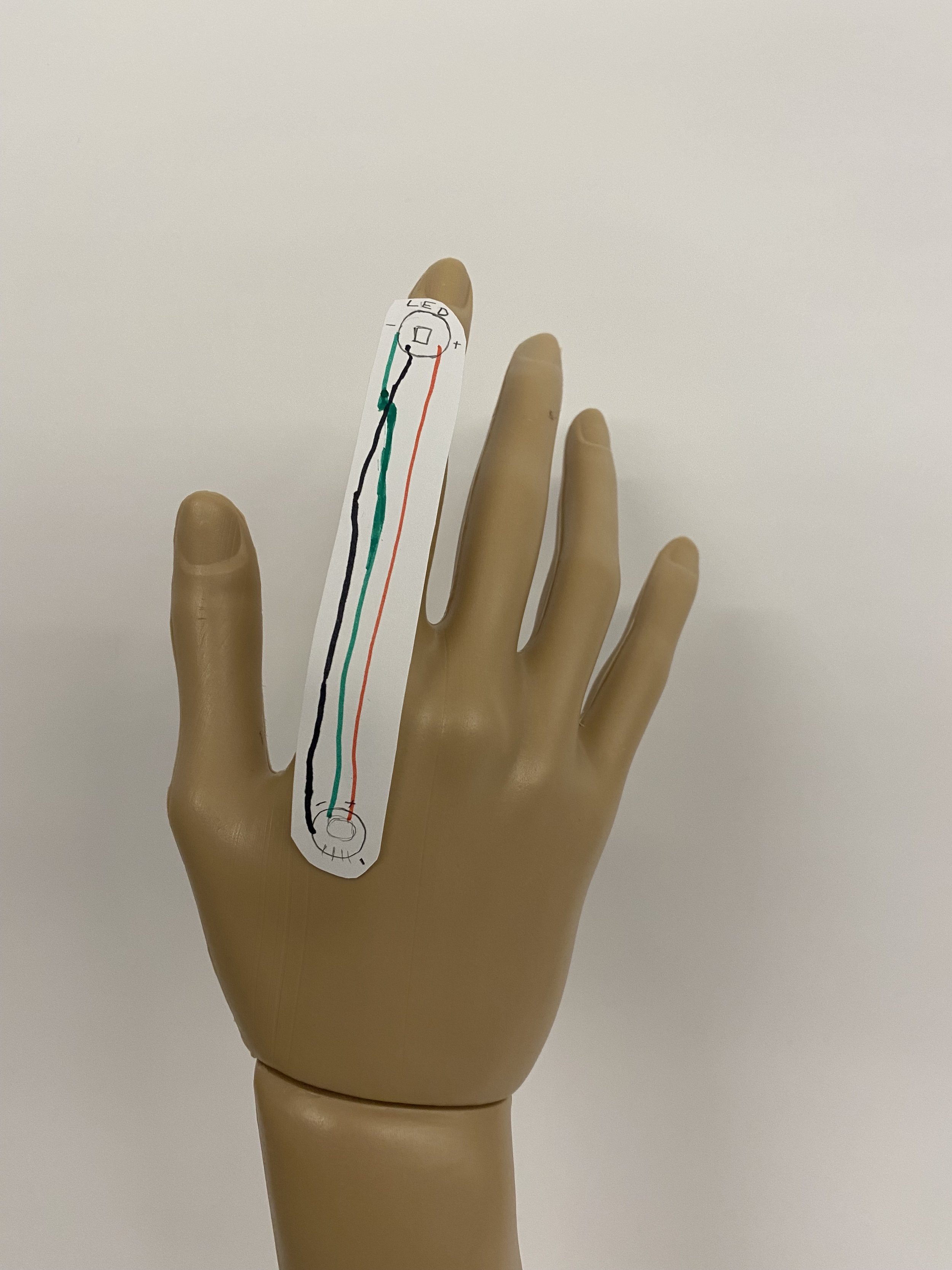
1. Follow the Diagram for constructing the circuit:
Be careful if you follow the image, numbers are flipped. Make sure that you connect to pin 1 not θ1.
2. First, connect ground from your processor board to the RGB LED marked with (-).
3. Connect the voltage lines marked by (+).
4. Finally, connect your desired IO pin to the IN tab on the LED.
1. Download and install the FastLED Library: For this tutorial, you will need to download the FastLED Arduino Library zip folder, and then install it as a library in your Arduino (For first timers, here are steps to install an Arduino library here).
The FastLED Arduino Library provides compatibility with many different types of RGB LEDs as well as a great deal of predefined color palettes and example code.
(Note that these are WS2812B RGB LEDs and this will have to be specified in any code you use with this library. Reference the code below to see how this is done.)

2. Upload Main Arduino Program to LilyTiny Microcontroller :
Download your main Arduino code via the link below, compile and upload to your TinyLily microcontroller:
#include <FastLED.h>
#define NUM_LEDS 1 //this is the number of LEDs in your strip
#define DATA_PIN 1 //this is the number on the silkscreen you want to use
#define COLOR_ORDER RGB

CRGB leds[NUM_LEDS];

int brightness = 20; //value from 0-255 to manipulate brightness

void setup() {
  FastLED.addLeds<WS2812B, DATA_PIN>(leds, NUM_LEDS);
  FastLED.setBrightness(brightness);
}

void loop() {
  for (int i = 0; i < 256; i++) {
    fill_rainbow(leds, NUM_LEDS, i, 256 / NUM_LEDS);
    FastLED.show(); //update the LEDs
    delay(100); //optional delay for slower fading
  }
}
The program should blend your LED(s) through the colors of the rainbow. If you're interested in creating other lighting effects, check out the example sketches included with the library. It is likely you'll have to change the defined number of LEDs, type of LED, and data pin.
IMPORTANT: if the LED is only lighting in green, that means there is an issue.
3. Once your Arduino code has been successfully uploaded into the LilyTiny microcontroller, you should see the LED lighting up and go through the colors of the rainbow!
4. Replace the programmer with TinyLily Battery Adapter and power with the battery in the tiny lily kit (so it can be standalone and no longer connected to laptop).


Tip: If you are getting errors when uploading, It may be helpful to remove the alligator clips from the TinyLily microcontroller when uploading the Arduino code. Here is a link for troubleshooting with compiling/uploading your Arduino code to the LilyTiny Microcontroller.
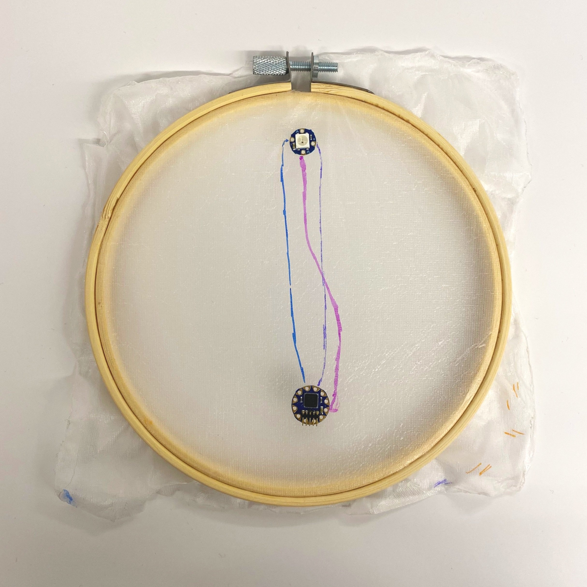
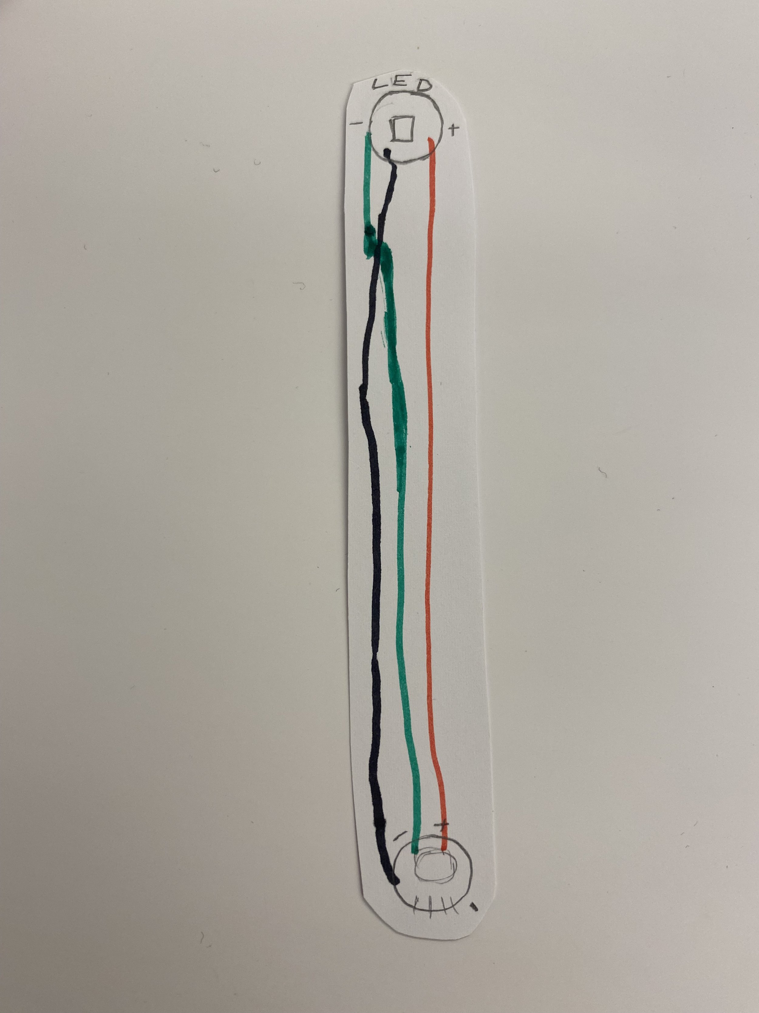
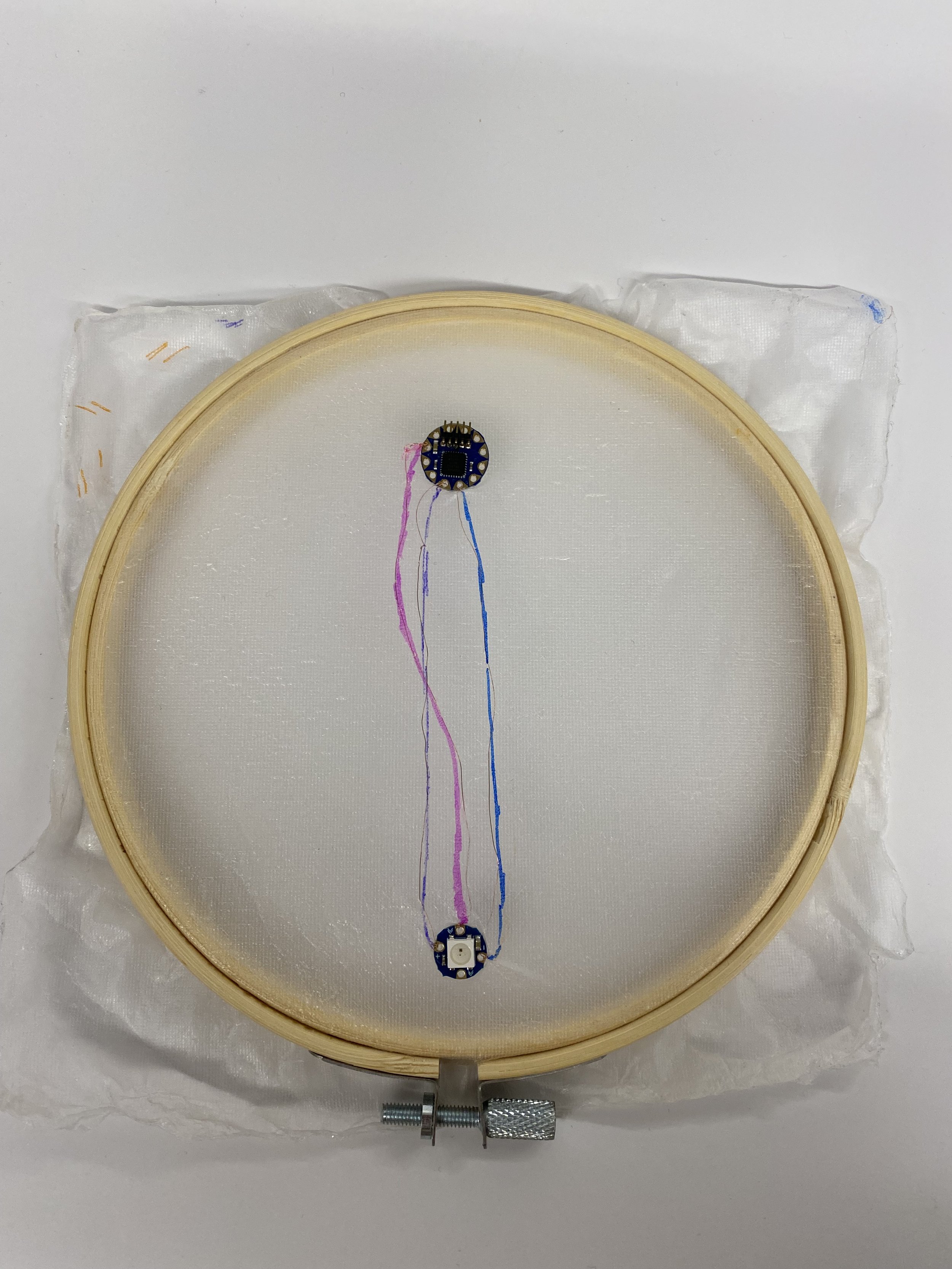
1. Plan out where you would like to place this circuit on the mannequin hand and sketch out the circuit layout on a piece of paper.
2. Place SkinCloth in the embroidery hoop. Once the SkinCloth is dry, place it into the embroidery hoop for the next steps of sewing.
IMPORTANT: The temporary tattoo silicone side (slippery side) should be facing up.
3. Based on your plan of the circuit in Step 1, use a pencil or pen to sketch out the placement of the components on the SkinCloth.

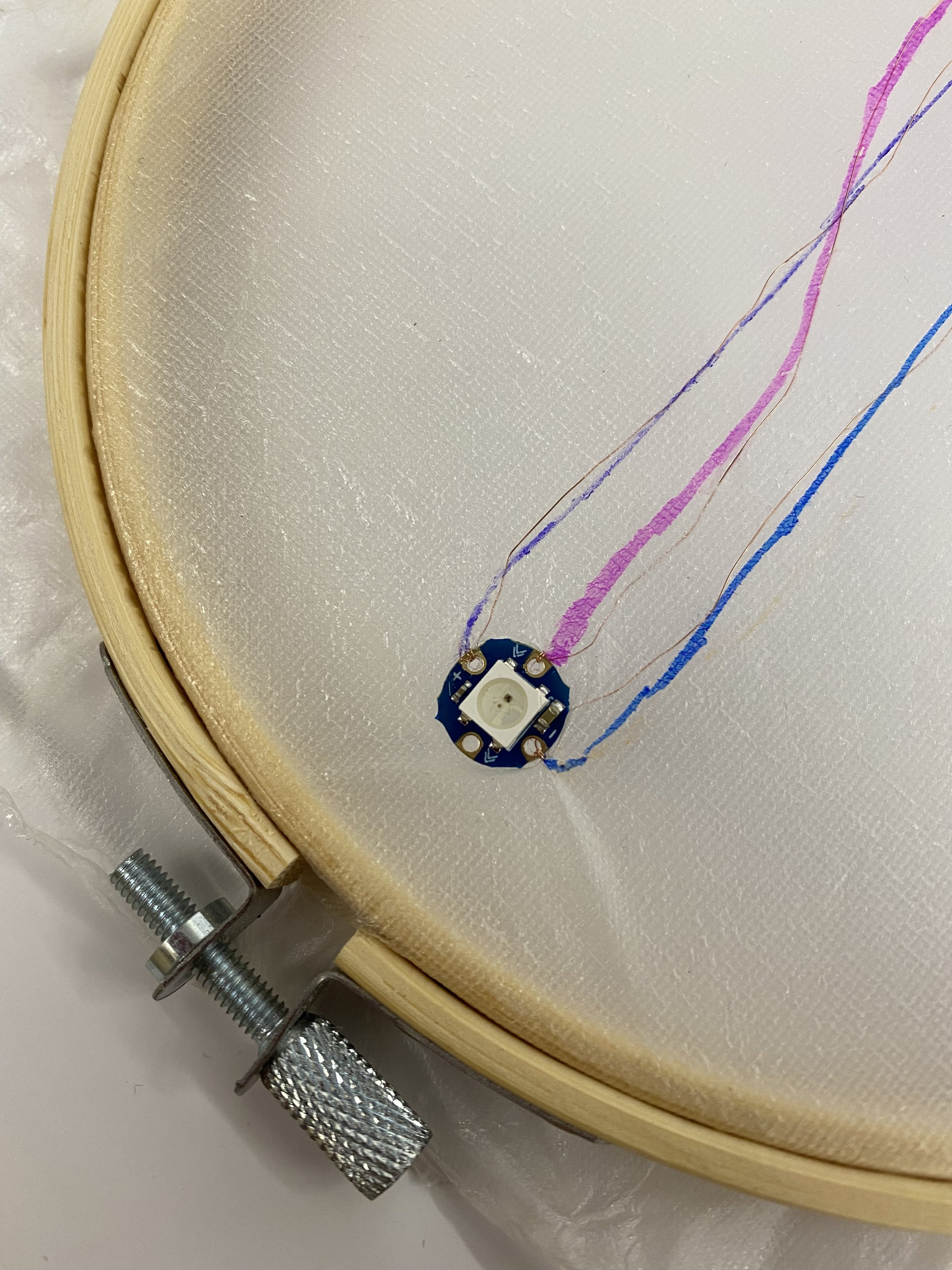
4. Sew and complete your circuit on the SkinCloth with the 36 gauge conductive wire. Note that the conductive wire is insulated!
IMPORTANT: Remember to sand down the ends of the wire to connect it to the leads (we need to do this since the wire is insulted!). One tip is to adhere down the TilyLily components to the SkinCloth to prevent it from moving around when sewing.
IMPORTANT: Remember to use the bronze conductive copper wire (36 gauge) for this step (NOT the silver conductive thread!)
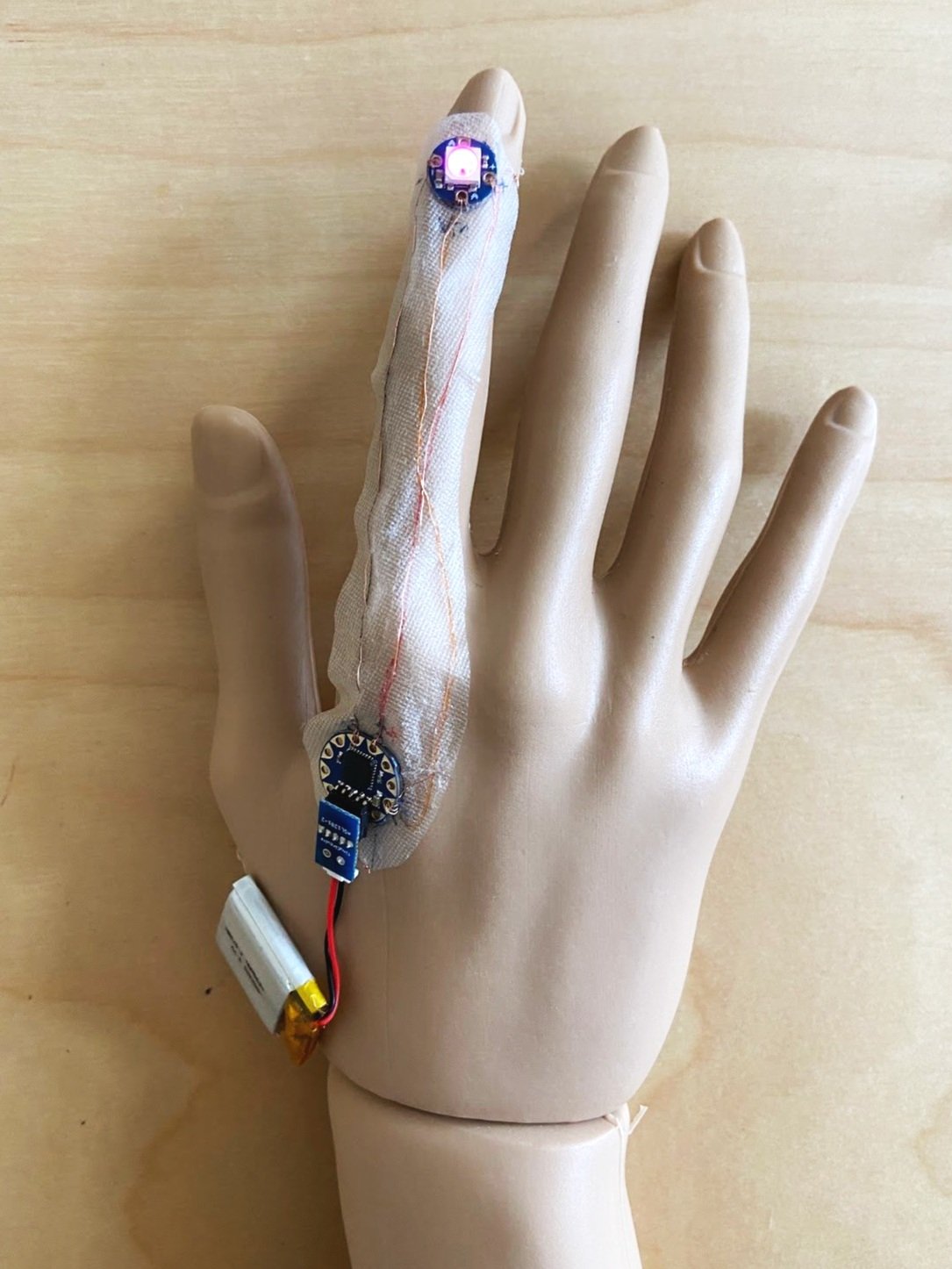
5. Once you are done sewing, attach the battery and see the RGB LED shine!!
Demo video on skin cloth:
Remove from the embroidery hoop, apply a layer of temporary tattoo adhesive (green sheet) underneath the skincloth, and apply on the mannequin. It may help to apply multiple layers of the temporary tattoo adhesive.


Demo video of final working prototype: https://drive.google.com/file/d/1upzkGojUDirwy5CInS8_ggMpdSeCnlZa/view?usp=sharing
How would you compare the SewSkin fabrication process with DuoSkin? Could you use DuoSkin instead of SewSkin to complete this lab?
What body locations do you think SewSkin is uniquely suited for?
Which part of the fabrication process did you find most challenging?
For your Lab 2 submission, construct your SewSkin RGB LED circuit. Post a photo of each onto the Canvas discussion board, with a 100-word description on what you made, responses to the reflection questions, and any challenges you encountered on the way.
Note: if you are already an experienced electronics builder you are encouraged to expand the project to match your skillset.
Q1: What are some common prototyping materials that can be used to connect circuit components as an alternative to copper wire?
Answer: Conductive thread, conductive tape, alligator clips, conductive ink, etc.
Q2: What is the avrdude: stk500_recv() error, and how to resolve the issue?
Answer: Check connections. Try to unplug and replug the wires or restart the Arduino to redo the uploading.


