Featured
Shieldex 235/36 dtex 4 ply +B Conductive Thread
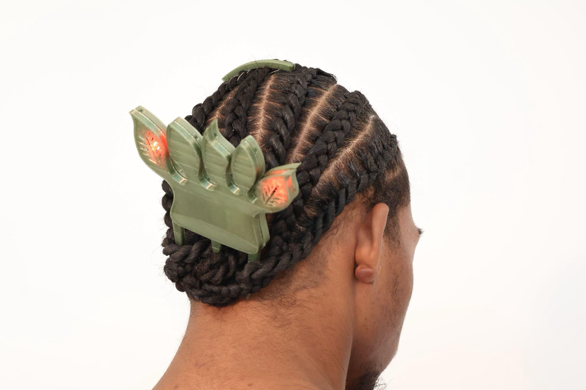
SkinLink Toolkit: MCU module, 2 NeoPixel RGB LED modules, connector modules
3D printed comb enclosure
3D printed anchor
Clear nail polish
Add six strands of conductive threads to the anchor, coat the top 3cm of conductive thread with clear nail polish to insulate them.
Use the anchor to separate the conductive threads, seprate the hair into three strands and put one conductive thread into each of the strands
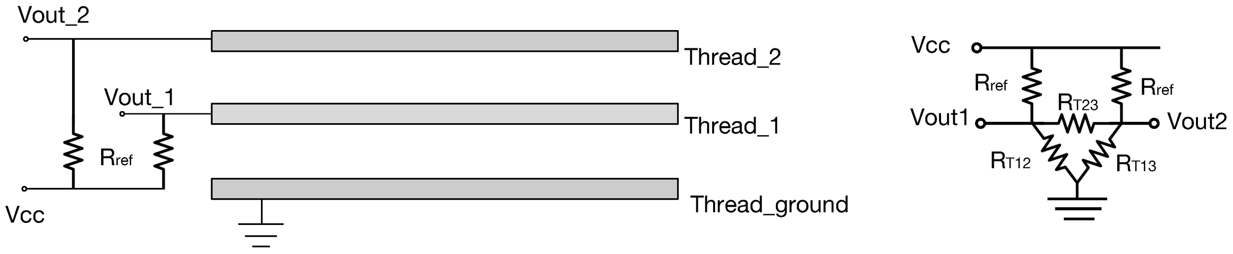
Braid two dutch braids, ensure the conductive threads are not shorting during the braiding process by using a multimeter to test continuity.
Solder 1MOhm resistor to the SkinLink connector modules based on the circuit diagram from https://www.mdpi.com/1424-8220/18/11/3775
Assemble SkinLink modules as shown in the image below
Connecting each end of the conductive thread to the SkinLink hardware through crimps.
Insert the comb to the bottom of the braids.
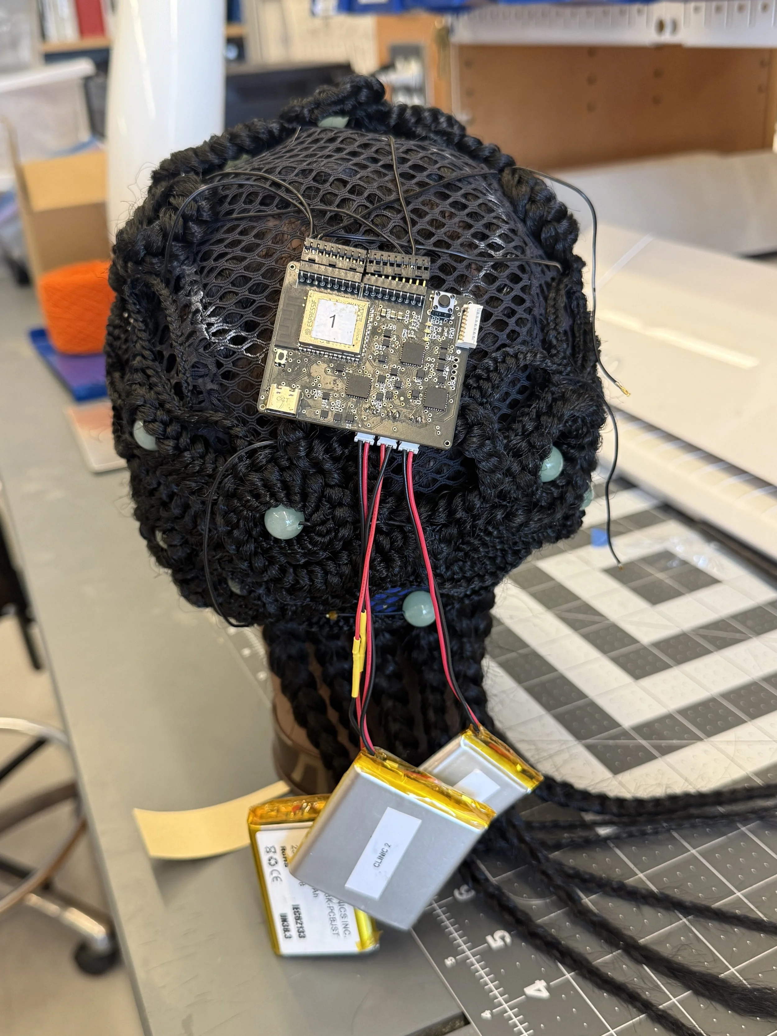
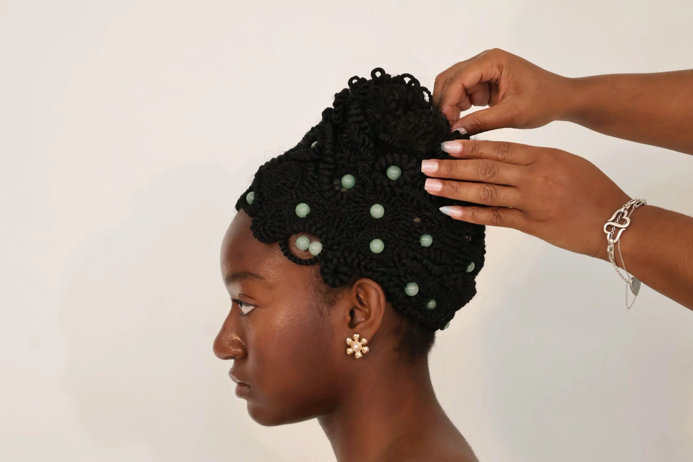
Premade Crochet Braids (16in or longer)
Large Mesh Elastic Crochet Cap
12mm Round Beads (around 30)
6 Pieces of Shape Memory Spring, 8 cm long, 0.5cm(5mm) coil diameter , 0.15 wire diameter, Pitch: wire size x2, transition temp 45C
Sillicon covered stranded wires
Use crimp connectors to connect each end of the SMA coils for easy soldering.
Insert SMA coil into a shrink tube for easy threading.
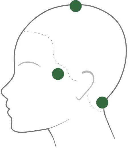
Thread the tube through the braid and beads in targeted areas: temple, top of head, and nape as shown in the diagram below.
Solder the SMA coil to wires, and connect the wires to the hardware from EdemaFlex (Link)
Drape the braids onto the mesh cap using pins, leave large area in the top of the head for hardware, and sew the braids after completing draping.
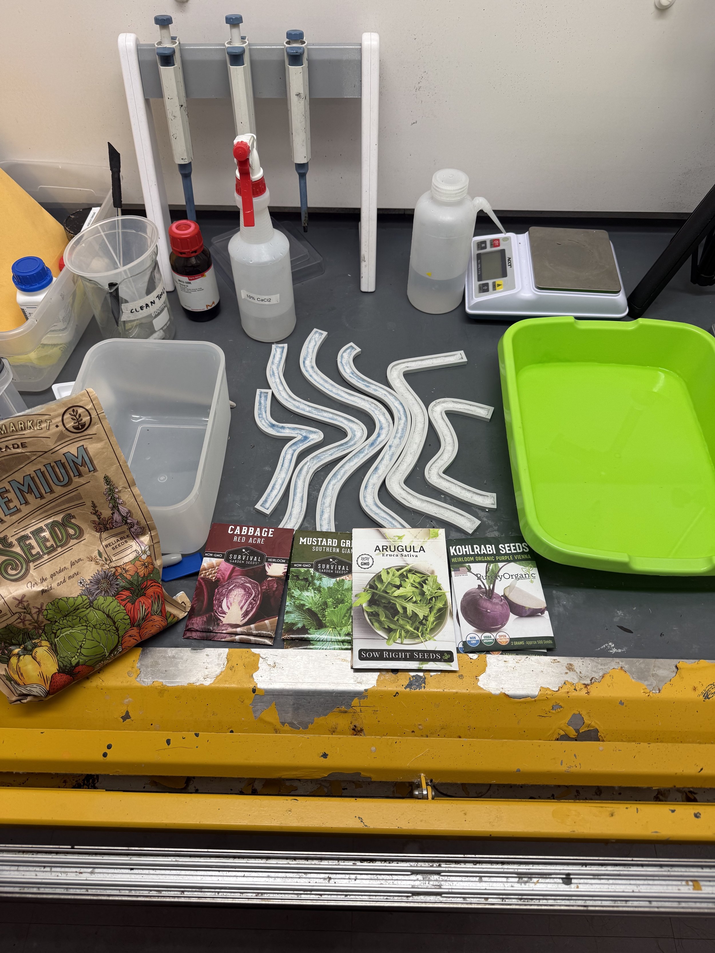
150 ml glass beaker
Syringe
4.5 g of sodium alginate
7.5 ml of glycerine
150 ml of water
3.75 ml of sunflower oil
600 ml of 10% calcium chloride solution
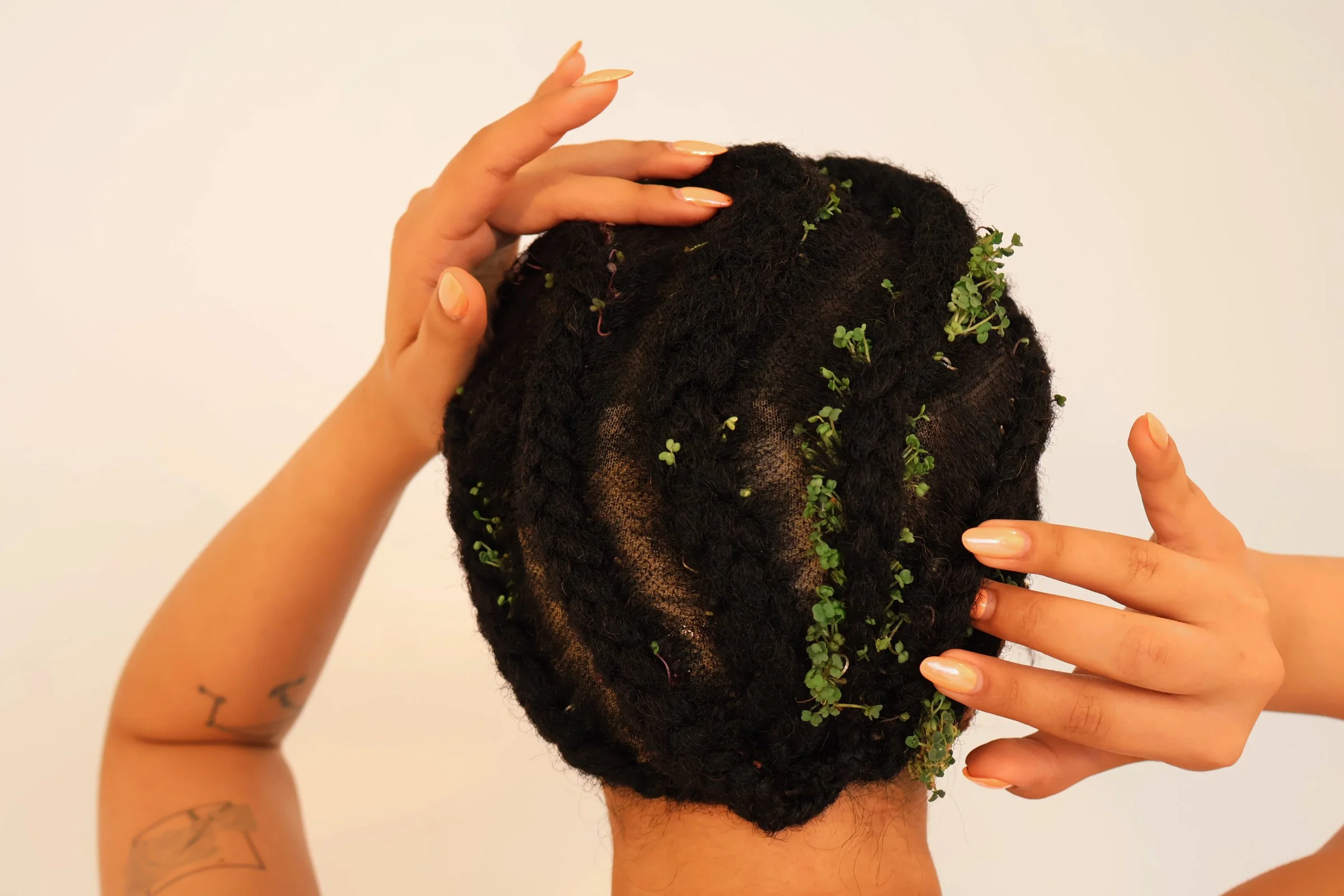
micro-green seeds (chia, arugula, purple cabbage, mustard, kohlrabi)
full lace human hair wig
cheese cloth
3D printed molds
food processor
vacuum sealer
a large liquid container for coagulation solution
Large plastic shower cap
Skin Safe Silicone Based Adhesive
Download the 3D models and print them with PLA filaments.
Add the glycerine, water, and oil to the food processor.
Add in alginate, mix until all lumps are removed.
Put mixture in the beaker.
Heat the mixture in a 60 degrees Celsius lab oven for 20 minutes.
Place the mixture in a vacuum sealer for 30 minutes.
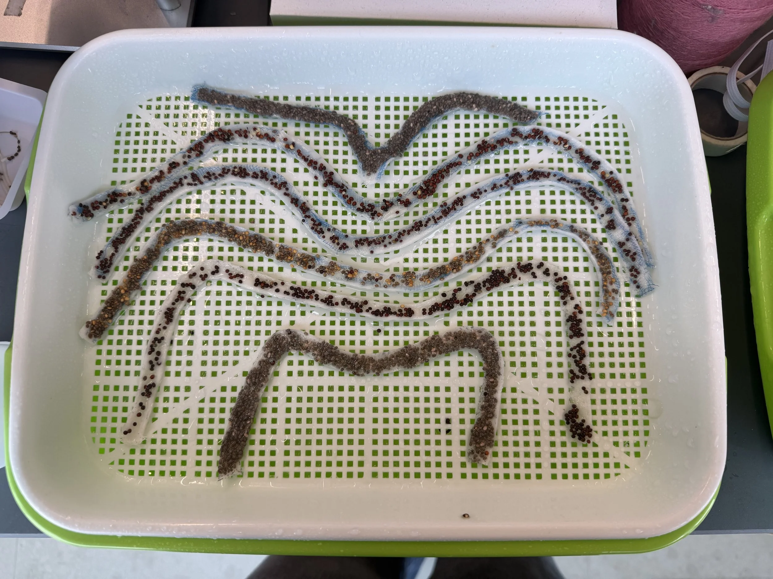
Cut the cheese cloth to fit in the bottom of each mold.
Add the mixture to the syringe, and fill each mold with the mixture.
Sprinkle seeds on top of mixture, one type of seed for each mold, two molds for chia seeds
Spray each mold with a generous amount of 10% CaCl, and place the lids on them.
Put 500ml CaCl in a large container, dip each mold with the lid attached inside the solution.
Place the biofilm in a dark and humid container for 3 days.
Wash, shampoo, and blow dry the wig.
Part the hair in 6 sections based on the 6 biofilm shapes.
For each braid, part each section in half, place biofilm in the center, then begin corn rows braiding.
After all braids are completed, spray the hair generously with water.
Cover wig in shower cap and placed in sunlight for 7 days.
Braid models hair into 2 french braids and wrap around the head
Wrap hair with plastic wrap
Place wig cap matching the model’s skin tone over plastic wrap
Cut excess lace from the wig.
Apply skin safe silicone adhesive all around the hairline and allow to become tacky. (Blowdryer helps)
Apply the wig and stick to adhesive one small area of the hairline at a time (hold firmly in place for 30 seconds.)
Isopropyl Alcohol (99-99.8%)
Isopropyl Alcohol (70%)
Formlabs Form3L Printer
Formlabs Clear Resin V4
Sandpaper (213Q P800-grit)
Aieenjor Water-Based Nail Polish
Nail Filer
X-acto Knife
UV Lamp
Nail Drill
SLA print the file of the nail design.
Carefully remove the 3D print from the build plate and soak in isopropyl alcohol (99-99.8%).
Cut the supports from the 3D print.
Once supports are removed, give a rinse in IPA for any remaining support debris.
Using super fine sandpaper (P800), sand all the 3D prints gently to remove any remnants of supports. If needed, you can take an X-acto knife and gently remove any little broken support pieces, but be careful not to cut the model itself.
Add 0.2 grams of red cabbage power to the water-based nail polish bottle.
Using a nail drill, mix the red cabbage power with the water-based nail polish.
Apply 8 layers of the pH nail polish to the nails. Wait for it to dry between each layer.
To test the color change under different pH conditions, prepare testing solutions at different pH levels. We used pH 4, 7, and 10 for this testing. Other alternative testing solutions include vinegar, bleach, water, and milk.
File the natural nails and the back of the nails with a nail filer.
Clean both the natural nails and the back of the nails with isopropyl alcohol (70%) and isopropyl alcohol (99-99.8%), respectively.
Apply a clear, double-sided adhesive nail sticker to the natural nail.
Attach the nails at a 45º angle from the nail bed to the nail tip.

Isopropyl Alcohol (99-99.8%)
Isopropyl Alcohol (70%)
Formlabs Form3L Printer
Formlabs Clear Resin V4
Sandpaper (213Q P800-grit)
ViniMay Metal Chrome Gel Nail Polish
Angelina nail supply Clear UV Top Coat
Nail Filer
X-acto Knife
UV Lamp
SLA print the file of the nail cover design.
Carefully remove the 3D print from the build plate and soak in isopropyl alcohol (99-99.8%).
Cut the supports from the 3D print.
Once supports are removed, give a rinse in IPA for any remaining support debris.
Using super fine sandpaper (P800), sand all the 3D prints gently to remove any remnants of supports. If needed, you can take an X-acto knife and gently remove any little broken support pieces, but be careful not to cut the model itself.
Apply 1 of the metal chrome nail polish to the nails. Cure with a UV lamp in between each layer.
Once dried, paint the nail cover with a clear UV top coat. Cure with a UV lamp.

Construct the controller circuit following the circuit schematic
It is recommended that the circuit be soldered onto a Perma-Proto Quarter-sized Breadboard PCB for easy use.
Optional: The controller PCB can be assembled inside a 3D-printed enclosure. The enclosure 3D file is attached. The enclosure can be printed either using a SLA printer or a FDM printer. The screws of the enclosure are M2-6 Socket Head Screws.
Connect the solenoid to the controller circuit.
Program the microcontroller through Arduino. The code can be downloaded below.
Power on the controller circuit either through a USB cable or using a tattoo machine power supply. The supply voltage should be 5V.
The solenoid should be activated in a linear actuation at a fast frequency. Turning the knob of the potentiometer, the speed of the solenoid would change: clockwise → faster speed; counterclockwise → slower speed. The indicator LED will also change color accordingly.
File the natural nail and the back of the nail cover with a nail filer.
Clean both the natural nail and the back of the nail cover with isopropyl alcohol (70%) and isopropyl alcohol (99-99.8%), respectively.
Apply a clear, double-sided adhesive nail sticker to the natural nail.
Attach the nail cover at a 45º angle from the nail tip to the nail bed.
Unstick the nail from left to right and remove the remaining sticker tab peeling it off with your fingers.


Isopropyl Alcohol (99-99.8%)
Isopropyl Alcohol (70%)
Formlabs Form3L Printer
Formlabs Clear Resin V4
Sandpaper (213Q P800-grit)
ViniMay Metal Chrome Gel Nail Polish
D&Z orange and turoquoise gel polish color 313 and 365
Dafu yellow gel polish color M045
Angelina nail supply Clear UV Top Coat
Nail File
X-acto Knife
UV Lamp
SLA print the two files of the ring and nail cover design.
Carefully remove the 3D print from the build plate and soak in isopropyl alcohol (99-99.8%).
Cut the supports from the 3D print.
Once supports are removed, give a rinse in IPA for any remaining support debris.
Using super fine sandpaper (P800), sand all the 3D prints gently to remove any remnants of supports. If needed, you can take an X-acto knife and gently remove any little broken support pieces, but be careful not to cut the model itself.
Apply one layer of the metal chrome gel nail polish to the nails. Cure with a UV lamp in between each layer.
Apply 3 layers of yellow, orange and turquoise gel nail polish to the nails. Make gradient of colors using a fluffy brush. Cure with a UV lamp in between each layer.
Once dried, paint the nail cover with a clear UV top coat. Cure with a UV lamp.

Construct the controller circuit following the circuit schematic.
It is recommended that the circuit be soldered onto a Perma-Proto Quarter-sized Breadboard PCB for easy use.
Program the microcontroller through Arduino. The testing code can be downloaded below.
When talking to the microphone, the on-board LED will dim according to the volume of the sound.
To visualize the sound, program the microcontroller through Arduino. The code can be downloaded below.
To connect the Arduino to the p5.js visualization, p5 serial control need to be installed: https://github.com/p5-serial/p5.serialcontrol
The p5.js visualization sketch: link

Construct the controller circuit following the circuit schematic.
It is recommended that the circuit be soldered onto a Perma-Proto Quarter-sized Breadboard PCB for easy use.
Program the microcontroller through CircuitPython. The testing code can be downloaded below.
To prepare the audio file, prepare the sound file in .wav format using the online recording tool: https://resonaterecordings.com/voice-recorder/
The .wav file needs to be renamed to “audio.wav” and saved to the CircuitPython folder when the microcontroller is connected to the computer.
File the natural nail and the back of the nail cover with a nail filer.
Clean both the natural nail and the back of the nail cover with isopropyl alcohol (70%) and isopropyl alcohol (99-99.8%), respectively.
Apply a clear, double-sided adhesive nail sticker to the natural nail.
Attach the nail at a 45º angle from the nail bed to the nail tip.
Unstick the nail from left to right and remove the remaining sticker tab peeling it off with your fingers.

Isopropyl Alcohol (99-99.8%)
Isopropyl Alcohol (70%)
Formlabs Form3L Printer
Formlabs Clear Resin V4
Sandpaper (213Q P800-grit)
Born Pretty Red Jelly Gel Nail Polish
Angelina nail supply Clear UV Top Coat
Nail Filer
X-acto Knife
SLA print the file of the nail cover design.
Carefully remove the 3D print from the build plate and soak in isopropyl alcohol (99-99.8%).
Cut the supports from the 3D print.
Once supports are removed, give a rinse in IPA for any remaining support debris.
Using super fine sandpaper (P800), sand all the 3D prints gently to remove any remnants of supports. If needed, you can take an X-acto knife and gently remove any little broken support pieces, but be careful not to cut the model itself.
Apply 2 layers of Born Pretty Red Jelly Gel nail polish to the nails. Cure with a UV lamp in between each layer.
Once dried, paint the nail cover with a clear UV top coat. Cure with a UV lamp.
Solder five laser diodes to each battery connector. The red wire connects to “SW,” and the blue wire connects to “-”.
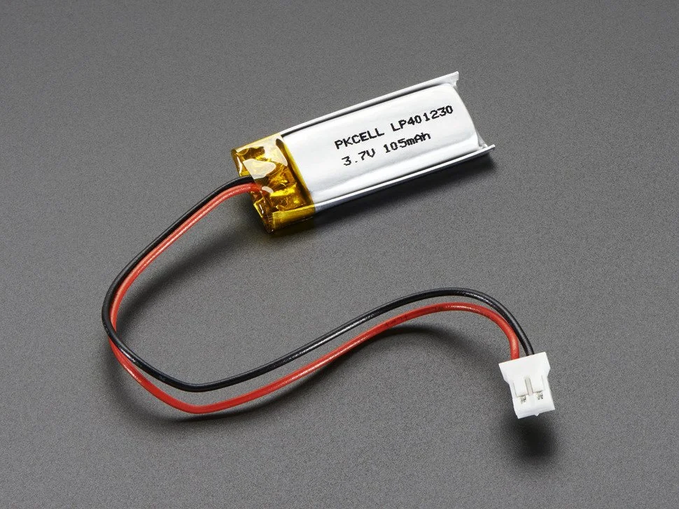
Connect 3.7V LiPo batteries to each of the battery connectors.
Before switching on the battery connector, ensure that the laser diode is not pointing at human eyes or camera lenses. Safety goggles are recommended.
File the natural nail and the back of the nail cover with a nail filer.
Clean both the natural nails and the back of the nails with isopropyl alcohol (70%) and isopropyl alcohol (99-99.8%), respectively.
Apply a clear, double-sided adhesive nail sticker to the natural nail.
Attach the nail cover at a 45º angle from the nail bed to the nail tip.

Isopropyl Alcohol (99-99.8%)
Isopropyl Alcohol (70%)
Formlabs Form3L Printer
Formlabs Clear Resin V4
Sandpaper (213Q P800-grit)
D&Z Black Gel Polish
Angelina nail supply Clear UV Top Coat
X-acto Knife
UV Lamp
SLA print the file of the necklace design.
Carefully remove the 3D print from the build plate and soak in isopropyl alcohol (99-99.8%).
Cut the supports from the 3D print.
Once supports are removed, give a rinse in IPA for any remaining support debris.
Using super fine sandpaper (P800), sand all the 3D prints gently to remove any remnants of supports. If needed, you can take an X-acto knife and gently remove any little broken support pieces, but be careful not to cut the model itself.
Apply two layers of the D&Z Black Gel Polish to the words of the necklace. Cure with a UV lamp in between each layer. After applying the final coat, cure with a UV lamp again.
Once dried, apply a clear UV top coat to the words of the necklace. Cure with a UV lamp.
Layout SkinLink modules inside each slot on the necklace, and adjust the placement accordingly to avoid bending the flexible connectors
Measure the length between each component, and prepare the SkinLink wiring connectors accordingly.
Program the SkinLink in Arduino. The code can be downloaded below.
One day in the future humans might be able to see in the dark without having to turn on a flashlight or wear night-vision goggles. In the meantime, with the aid and versatility of SkinLink, we have AutoLight: A hands-free wearable eyebrow mount that uses an ambient light sensor to turn on automatically in low-light.
Autolight is made up of a SkinLink MCU module, an ambient light sensing module, and a white neopixel LED module as well as elastic resin printed housings for the skin link module, light sensor, and LED.
Aesthetically inspired by the Borg from Star Trek, it boasts a rather conspicuous cyberpunk aesthetic, in hopes to push humans further toward an augmented future with new abilities.
Elastic 50A Formlabs resin tank
SkinLink MCU module
Ambient Light Sensing Module
Neopixel RGB LED Module
Create a design with structures that accommodate the SkinLink MCU module, Ambient Light Sensing Module, and Neopixel RGB LED Module
Open the .stl in PreForm and print it on a Formlabs From 3 printer in clear resin
Soak in isopropanol alcohol bath after print
Color the prints with acrylic paint to match the desired skin tone
Layout SkinLink modules on face, adjust the placement accordingly to avoid bending the flexible connectors
Program SkinLink in Arduino
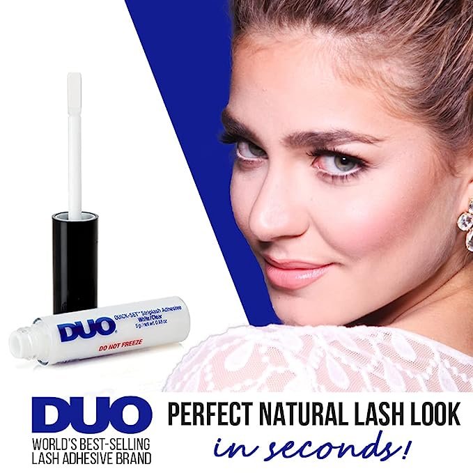
Attach the MCU module with DUO eyelash glue
Attach the cover for the MCU with DUO eyelash glue
Attach the housing of sensor and LED modules with DUO eyelash glue
Insert sensor and LED module into their corresponding housings
Insert the battery onto the battery connector on MCU module, tuck the battery behind the ear
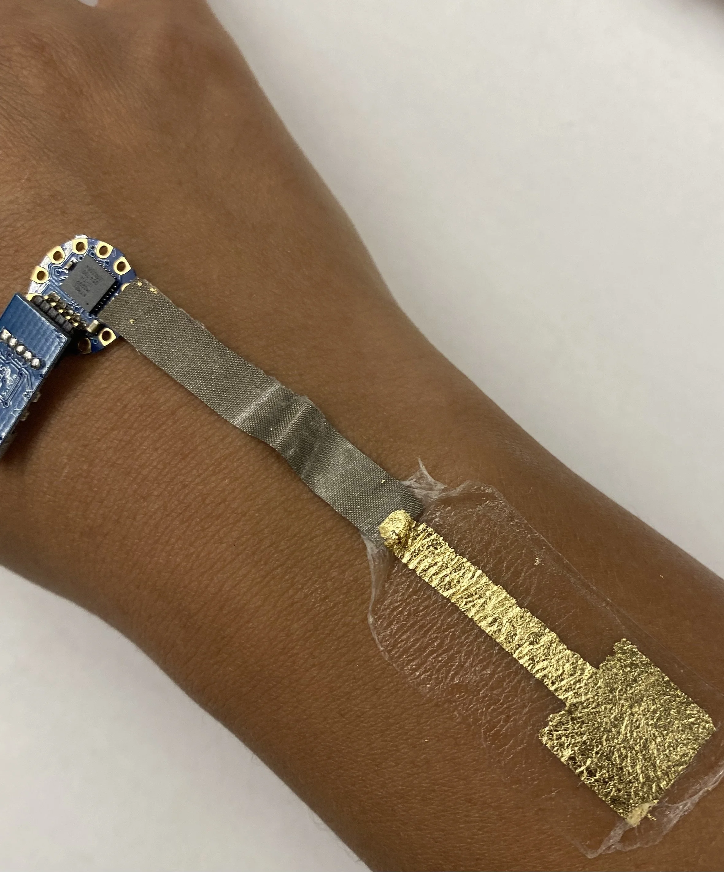
Pain relief envisioned as something you could wear while going out at night. Current heating patches are squares or ovals. ThermalDermal proposes any one-line shape as the substrate for heat. In the example below, it is pictured as a “hot tramp stamp”. A wearable patch that is both physically and conceptually hot.
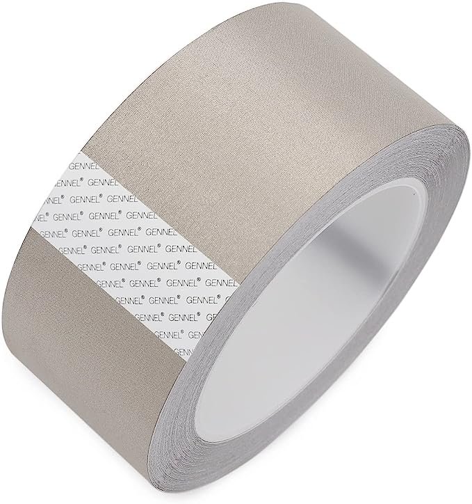
Gennel conductive cloth fabric adhesive tape
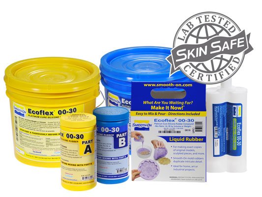
Ecoflex silicone 00-30
Thermochromic pigment
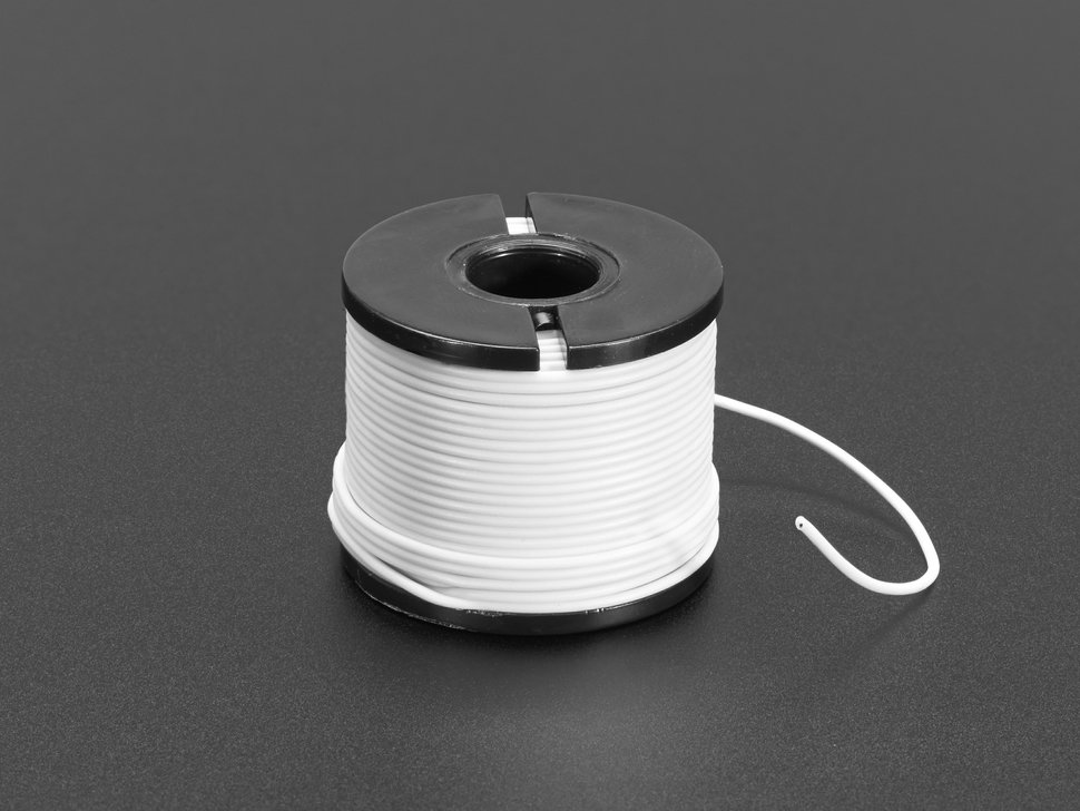
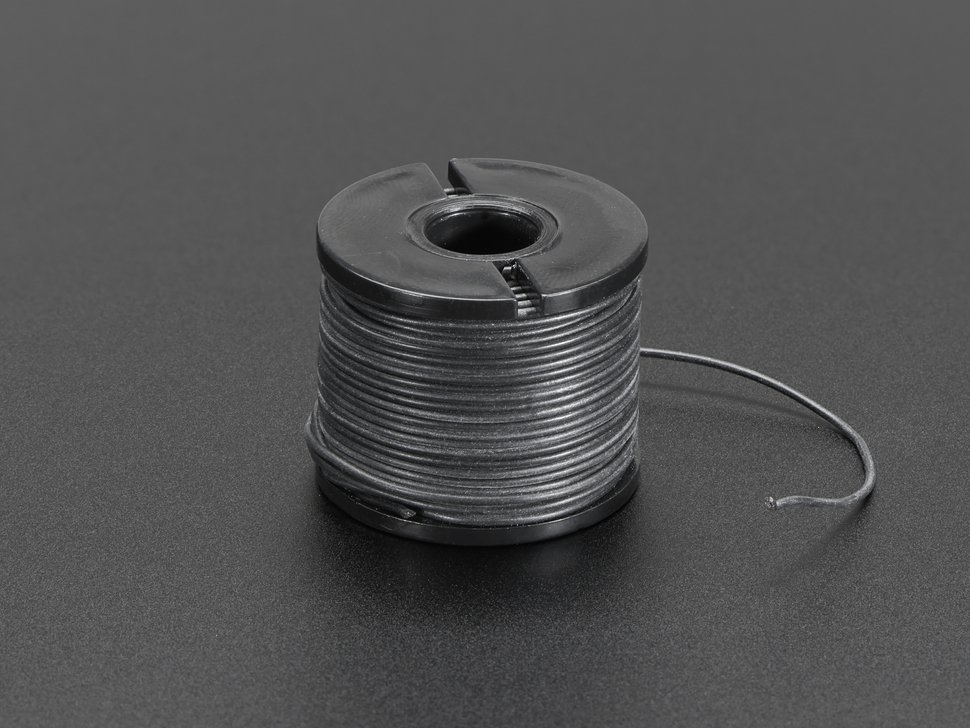
Silicone Cover Stranded-Core Wire - 50ft 30AWG White
Vinyl cutter
Xacto blade or box cutter
Create a 4mm thickness of one-liner 2D design, avoid any intersections
Import the design into Silhouette, vinyl cut it on conductive fabric tape
Remove the negative area of the tape
Measure the resistance of the trace, ideal resistance is around 10 ohms.
Solder wires onto each end of the trace
Mix 5 grams of part A and 5 grams of part B of Ecoflex
Add 0.5 grams of thermochromic pigments
Place the vinyl cut tape on a flat surface, pour the silicone mixture onto the vinyl cut tape to achieve an even layer
After the silicone fully cures, flip it and cut out the shape with a Xacto knife
Microporous tape layered across to create desired thickness
Layered uline tape over to desired thickness
Place tattoo on top right side facing out and cut tape layers to fit tattoo
Stick to skin or plastic backing to store
Imagining current wearables less as something to hide and more as something to flaunt and show off. Hearing aids typically tuck discreetly behind the ear for minimal visibility. This project rests in front of the ear, proudly showing off its audacious sculptural and material form.
It mimics a common tattoo motif of an angel whispering in an ear, but doubles as a functional object, amplifying sound. The angel is literally whispering!
Formlabs clear resin
Hearing Aid
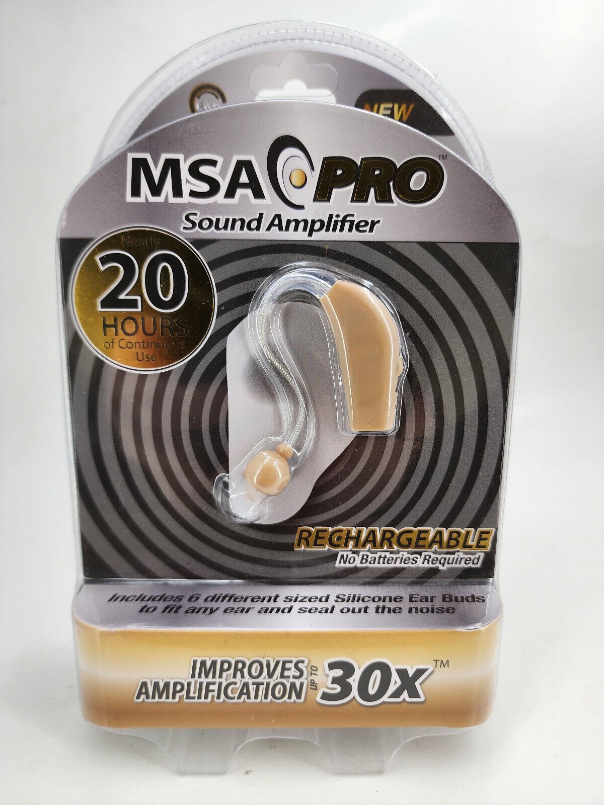

disassemble the hearing aid using a screwdriver
Apply hot glue around the wire connection to PCB
Download an ear 3D model
Pose a human mesh around it
Use a boolean to remove the shape of the ear from the model
Use another boolean to accommodate the PCB of the hearing aid
Export .stl file
Open the .stl in PreForm and print it on a Formlabs From 3 printer in clear resin
Soak in isopropyl alcohol bath after print
Insert the hearing aid PCB into the 3D print
Apply dots of hot glue onto non-essential areas


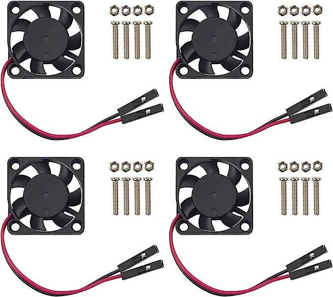
Picturing the surface of the human body as no different from that of a car or personal computer. In the future there might be an increasing need to cool embedded implants. Using 3D printed elastic resin, real PC fans are “installed” onto the surface of skin.
Elastic 50A Formlabs elastic resin tank
Fan
Battery
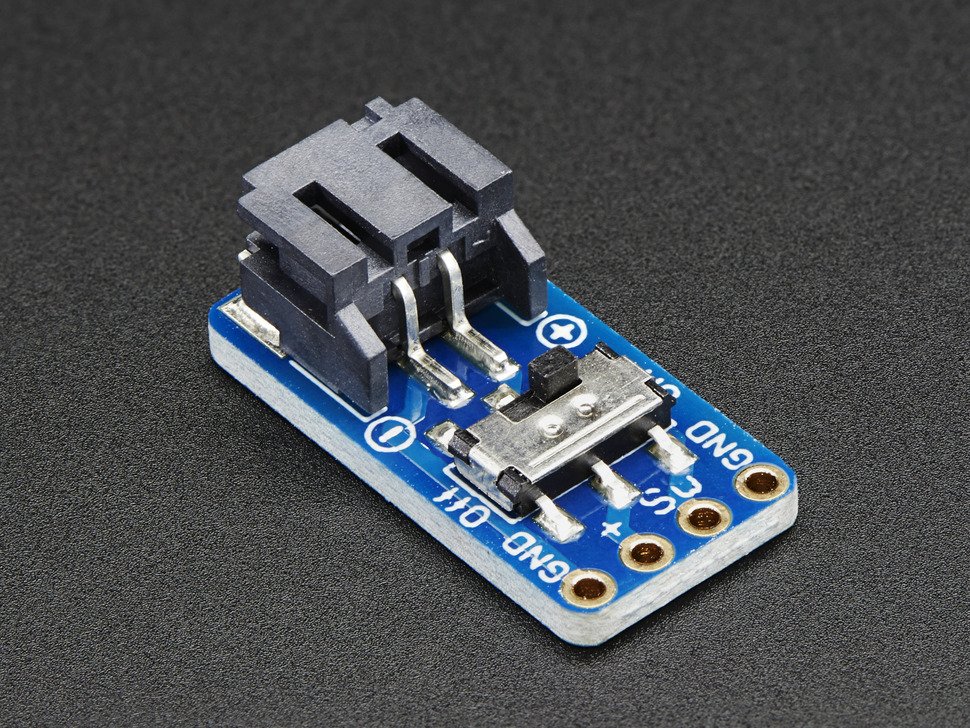
Switch connector
Wires
Silicone Cover Stranded-Core Wire - 50ft 30AWG White
Silicone Cover Stranded-Core Wire - 50ft 30AWG Black


Open the .stl in PreForm and print it on a Formlabs Form 3 printer in elastic 50A resin
Soak in isopropyl alcohol bath after print
Desolder wires on the fan, solder silicone-coated stranded wire to the fan, note the polarity: white for + and black for -
Fitting soldered fans into the 3D print
Feed the wires through the channels in the 3D print
Solder the wires to the battery connector, white wires -> SW, black wires -> GND
Clean with alcohol swab as needed
Use DUO eyelash glue to apply the CoolingUnit on skin


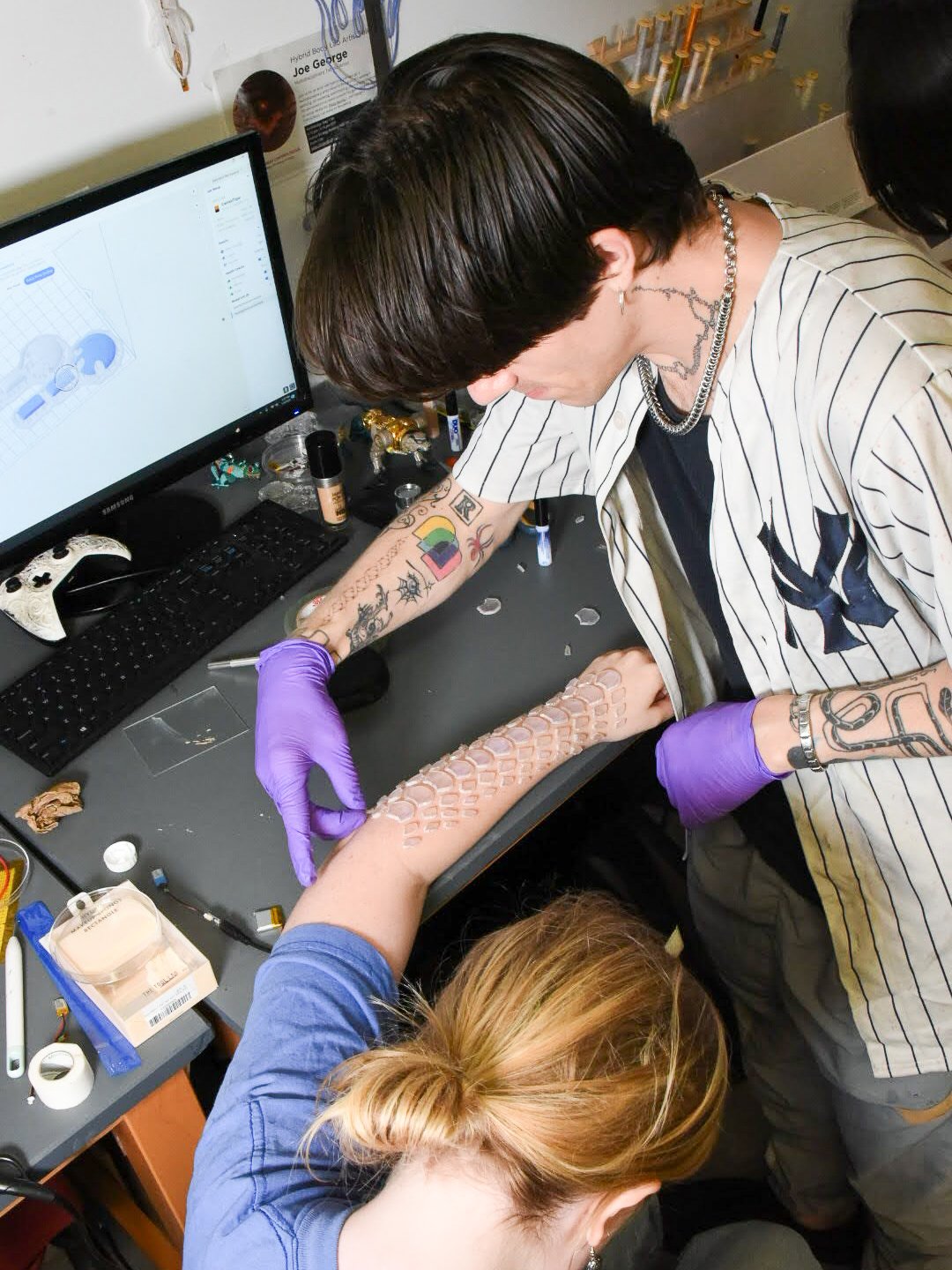
UV Scale is a set of flexible resin printed scales that will visually change color under UV light. The scales are to be applied on the skin using a safe skin adhesive in a pattern which emulates a snake's skin as it basks in the sunlight. The pattern of snake skin is an irregular sort of tessellation that easily and naturally warps with the unusual geometry of the human body.
Elastic 50A Formlabs resin tank
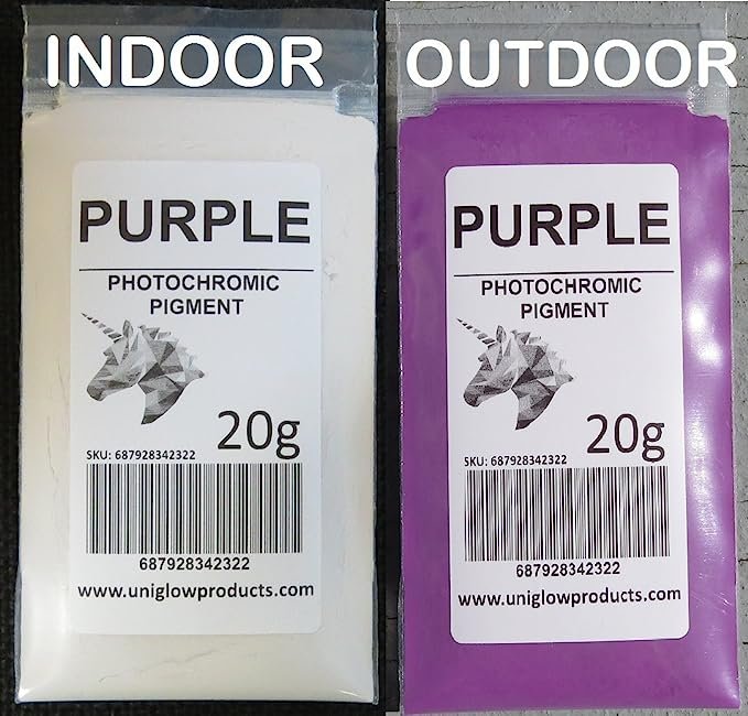
Photochromic pigment
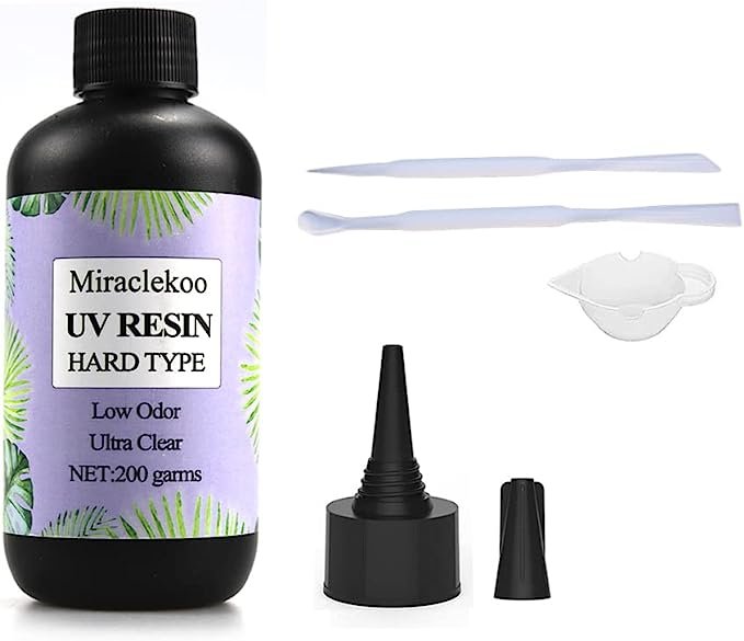
UV Resin soft type
DUO eyelash glue

Convert .svg file of scale 2D design to mesh in Blender
Extrude the plane to desired thickness
Export as .stl file
Open the .stl in PreForm and print it on Formlabs From 3 printer in elastic 50A resin
Mix 1 gram of purple photochromic pigment into 5 grams of UV resin soft type
Apply the mixture on the edges of each scale piece with a paintbrush
Curing under a UV lamp for 2 minutes
Apply DUO eyelash glue onto the bottom of each piece, wait for it to turn tacky and apply them onto skin.


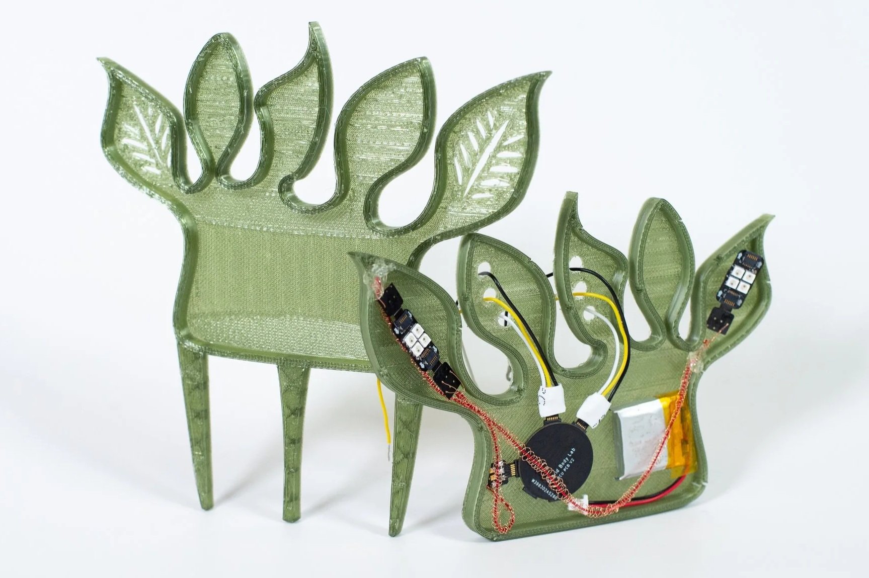
Social Prosthesis is a moving appendage designed as two headpieces made from rigid and soft structures. The soft skin of the prosthesis curls and contracts when triggered by touch on the face.
Social Prosthesis is made up of 3D resin print, silicone skin, and an embedded shape memory alloy circuit attached to a Duoskin capacitive touch.
Referencing the definition of prosthetic sociality, written by Mimi Thi Nguyen in the 2003 essay Queer Cyborgs and New Mutants, Social Prosthesis is an exploration of how technologies enhancing the human body create meanings that extend past the merging of biological and artificial—that must contest with the social and political contexts of its time.
EcoFlex NearClear 00-45
Shape Memory Alloy Spring, 0.5cm(5mm) coil diameter , 0.15 wire diameter, Pitch: wire size x2, transition temp 45C
Mold for silicone casting
Isopropyl Alcohol 99% - 99.8%
Resin printer
Korea Crystal Tec Transparent Stretchy Beading Line String 0.5 (or any thin, stretchy elastic to hold the nosepiece in place)
Sandpaper (3M Wetordry 213Q P800-grit)
Silicone Pigment (optional—for coloring silicone)
Alcohol Ink (optional—for coloring resin)
Art Resin (optional—for glossing resin)
32 AWG Copper Wires
15k Resistor
SOT23 Breakout Board (as perf board)
Multimeter
Optional: Isopropyl Mysristate


Resin Print
1. SLA print the two files of the Social Prosthesis design.
2. Carefully remove the 3D print from the build plate and soak in isopropyl alcohol (99-99.8%)
3. Cut the supports from the 3D print. The design has delicate and thin details, so it is important to remove the supports to determine that you are not cutting parts of the model.
4. Once supports are removed, give a rinse in IPA for any remaining support debris.
5. Using super fine sandpaper (P800), sand all the 3D prints gently to remove any remnants of supports. If needed, you can take an X-acto knife and gently remove any little broken support pieces, but be careful not to cut the model itself.
1. If you want to color the resin at this step, you can take alcohol ink and dilute it using isopropyl alcohol to achieve the desired opacity. Then, taking a paintbrush, coat the resin structures with the alcohol ink mixture. The resin will absorb the alcohol ink.
2. If you would like to gloss the resin at this step, take Art Resin and mix equal parts resin (black cap) and hardener (white cap) in a I1:1 ratio in a separate container with a disposable popsicle stick or paintbrush. Be sure to replace the caps correctly on the bottles when complete.
3. Using a (disposable) paintbrush, lightly coat the Art Resin on the resin print surfaces that require gloss. Allow to dry for at least 24 hours.
NOTE: Avoid putting the Art Resin on the surfaces that you want to stick to the face, to avoid creating a slippery surface for makeup application.

Circuit Schematic
1. Construct circuit following the circuit schematic
2. Crimp the ends of the SMA before silicone casting, in preparation to be soldered to the circuit.
1. Using a multimeter, test both ends of the SMA to ensure conductivity.
2. Using a DC power supply, you can test the curling of the silicone to ensure that it is moving as desired.
3. To reset: wait until SMA has cooled, and then manually stretch the SMA back to its maximum length.
1. Power the circuit with LiPo battery
2. Turn on switch on the Gemma M0, onboard LED shows yellow
3. Touch temporary tattoo, onboard LED turns purple
4. SMA should start shrinking
5. Wait for 45 seconds
6. SMA shrinking stops, onboard LED turns cyan

Silicone casting with purple color
1. Measure approximately 8g of Part A and approximately 8g of Part B of Ecoflex Near Clear 00-45.
2. Mix the two equal parts thoroughly using a popsicle stick.
OPTIONAL: to color the silicone, drop a pinprick of silicone dye into the clear mixture and mix. If you are trying to make a clear-colored gradient, create a separate silicone mixture with a colored dye.
4. Place into degassing chamber for 10 min to remove any air bubbles
5. Place SMA spring into mold and arrange to be cast into the silicone
6. Pour carefully into the mold, covering the SMA. Make sure the ends of the SMA are uncovered
7. Use a mixing stick or other tool to pop any extra air bubbles
8. Let cure for 4 hours.
9. When cured, carefully remove the silicone from the mold.

Skin Application
1. To apply the headpiece, you can take 3rd Degree and mix a pea-sized amount of Part A and B to create a silicone adhesive for the skin.
2. Once mixed, apply a thick layer to the back of headpiece on the areas that will contact the forehead
3. Press the headpiece with the silicone adhesive to the forehead and hold for 1 minute to let the product cure.
4. Gently test to make sure the headpiece is adhered to the skin. It will not be a super tight hold, but effective enough to hold up the piece securely while also easy to remove after.
5. To apply the nosepiece, hold the nose bridge of the piece to the nose (as if putting on glasses). Use the elastic band to secure in place.
6. The circuit should also be lifted to hide behind the head.
1. Gently peel the piece off, and remove the silicone adhesive from the back of the headpiece. It should come off in one piece.
2. Use isopropyl Myristate to remove any extra residue


